
For the Ford F150 pickup and super crew 1997, 1998, 1999, 2000, 2001, 2002, 2003 model year.
Cigarette lighter fuse – (fuse box in passenger compartment, fuse №3/20A) |
MENU
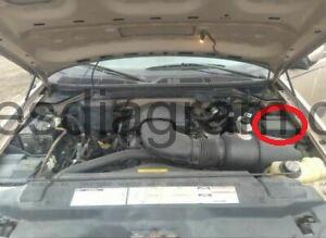
Power distribution box location 1997-1998
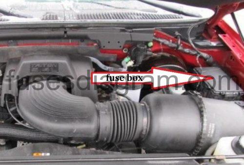
Power distribution box location 1999-2003
- Fuse box diagram (1999 model year)
- Fuse box diagram (2000-2001 model year)
- Fuse box diagram (2002 model year)
- Fuse box diagram (2003 model year)
Passenger compartment fuse panel 1997-2003
- Fuse box layout 1997
- Fuse box layout 1999
- Fuse box diagram Ford F150 2000-2001
- Fuse box layout 2002-2003
Primary battery fuses (megafuses)
Power distribution box 1997-1998.
Power distribution box is located in driver’s side of engine compartment.
Fuse box diagram (1997, 1998 model year).
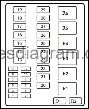
legend (1997, 1998 model year).
| Position | Amps | Description |
|---|---|---|
| 1 | 20A | Trailer tow back-up and tail lamps |
| 2 | 10A | Air bag diagnostic monitor |
| 3 | 15A | Power locks or not used |
| 4 | 15A | Air suspension or not used |
| 5 | 20A | Horn |
| 6 | 15A | Audio system |
| 7 | 15A | Parking and tail lamps |
| 8 | 30A | Headlamps |
| 9 | 15A | Daytime running lamps and fog lamps |
| 10 | 25A | Auxiliary power point |
| 11 | Not used | |
| 12 | Not used | |
| 13 | Not used | |
| 14 | 60A/20A | 4WAB rear anti-lock brake/ignition switch |
| 15 | 50A | Air suspension compressor or not used |
| 16 | 40A | Trailer tow battery charge and stop/turn lamps |
| 17 | 30A | 4WD transfer case shift motor and clutch |
| 18 | 30A | Driver power seat |
| 19 | 20A | Fuel pump |
| 20 | 50A | Instrument panel fuse panel ignition switch feed |
| 21 | 50A | Instrument panel fuse panel ignition switch feed |
| 22 | 50A | I/P fuse panel battery feed |
| 23 | 40A | I/P blower |
| 24 | 30A | PCM power |
| 25 | 30A | Power windows |
| 26 | 20A | Not used or Power locks |
| 27 | Not used | |
| 28 | 30A | Trailer tow electronic brake |
| 29 | Not used | |
| D1 | Rear ABS diode | |
| D2 | PCM diode | |
| R1 | Windshield wipers HI/LO speed | |
| R2 | Windshield wipers run/park relay | |
| R3 | Washer pump relay | |
| R4 | Fuel pump relay | |
| R5 | Horn relay | |
| R6 | PCM power relay |
Power distribution box 1999-2003 Ford F150.
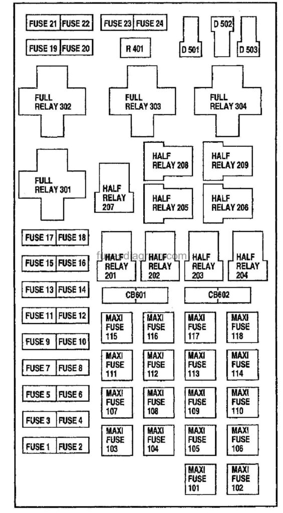
Fuse box diagram (1999 model year).
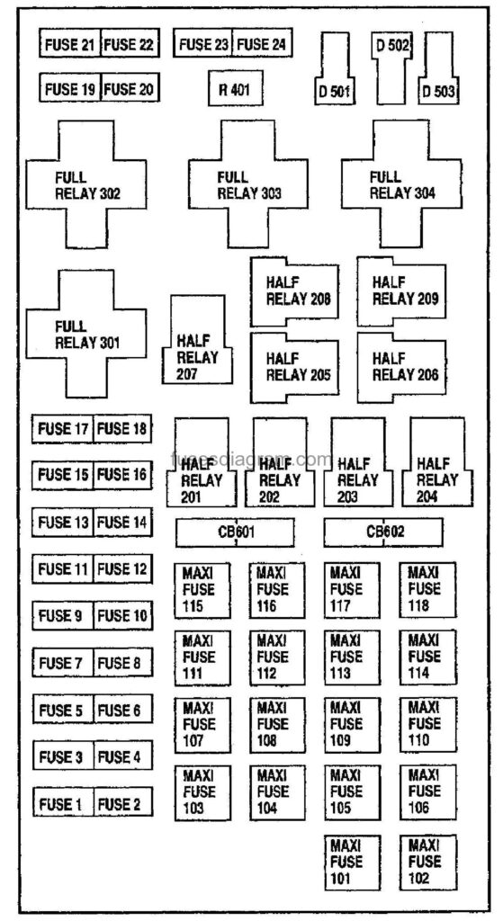
Assignment of the fuses (1999).
| Fuse/Relay Location | Fuse Amp Rating | Description |
|---|---|---|
| 1 | 25A * | Power Point |
| 2 | 30A* | Powertrain Control Module |
| 3 | 30A* | Headlamps/Autolamps |
| 4 | 15 A* | Air Suspension |
| 5 | 20 A* | Trailer Tow Backup/Park Lamps |
| 6 | 15 A* | Parklamps/Autolamps |
| 7 | 20A* | Horn |
| 8 | 15 A* | Power Door Locks |
| 9 | 15 A* | Daytime Running Lamps (DRL), Fog Lamps |
| 10 | 20A* | Fuel Pump |
| 11 | 20A* | Alternator Field |
| 12 | — | Not Used |
| 13 | — | Not Used |
| 14 | — | Not Used |
| 15 | — | Not Used |
| 16 | — | Not Used |
| 17 | — | Not Used |
| 18 | 15A* | Powertrain Control Module, Fuel Injectors, Fuel Pump, Mass Air Flow Sensor |
| 19 | 10 A* | Trailer Tow Stop and Right Turn Lamp |
| 20 | 10 A* | Trailer Tow Stop and Left Turn Lamp |
| 21 | — | Not Used |
| 22 | Not Used | |
| 23 | 15 A* | Powertrain Control Module, HEGO Sensor, Canister Vent |
| 24 | 15 A* | Powertrain С ontrol Module, Automatic Transmission, CMS Sensor |
| 101 | 30A** | Trailer Tow Battery Charge |
| 102 | 50/20A** | Four Wheel Antilock Brake Module/Rear Wheel Antilock Brake Module |
| 103 | 50A* | Junction Block Battery Feed |
| 104 | 30A** | 4×4 Shift Motor & Clutch |
| 105 | 40A** | Climate Control Front Blower |
| 106 | — | Not Used |
| 107 | — | Not Used |
| 108 | 30A** | Trailer Tow Electric Brake |
| 109 | 50A** | Air Suspension Compressor |
| 110 | 30A** | Power Windows |
| 111 | 50A** | Ignition Switch Battery Feed (Start and Run Circuits) |
| 112 | 30A** | Drivers Power Seat |
| 113 | 50 A** | Ignition Switch Battery Feed (Run and Accessory Circuits) |
| 114 | — | Not Used |
| 115 | — | Not Used |
| 116 | — | Not Used |
| 117 | — | Not Used |
| 118 | — | Not Used |
| 201 | — | Trailer Tow Park Lamp Relay |
| 202 | — | Front Wiper Run/Park Relay |
| 203 | — | Trailer Tow Backup Lamp Relay |
| 204 | — | A/С Clutch Relay |
| 205 | — | Horn Relay |
| 206 | — | Fog Lamp Relay |
| 207 | — | Front Washer Pump Relay |
| 208 | — | Not Used |
| 209 | — | Front Wiper Hi/Lo Relay |
| 301 | — | Fuel Pump Relay |
| 302 | — | Trailer Tow Battery Charge Relay |
| 303 | — | Rear Air Suspension Relay |
| 304 | — | Powertrain Control Module Relay |
Fuse box diagram (2000-2001 model year).
Assignment of the fuses (pickup and super crew 2000-2001).
| Fuse/Relay Location | Fuse Amp Rating | Power Distribution Box Description |
|---|---|---|
| 1 | 20A * | Power Point |
| 2 | 30 A* | Powertrain Control Module |
| 3 | 30A* | Headlamps/Autolamps |
| 4 | — | Not Used |
| 5 | 20A* | Trailer Tow Backup/Park Lamps |
| 6 | ISA* | Parklamps/Autolamps, Passenger Fuse Panel Feed Fuse #18 |
| 7 | 20 A* | Horn |
| 8 | 15A | Power Door Locks, CSM, Lock Relays (Except super crew) or Not Used |
| 9 | 15A* | Daytime Running Lamps (DRL), Fog Lamps |
| 10 | 20 A* | Fuel Pump |
| 11 | 20 A* | Alternator Field |
| 12 | 20A* | Rear Auxiliary Power Point |
| 13 | 15 A* | A/С Clutch |
| 14 | — | Not Used |
| 15 | — | Not Used |
| 16 | — | Not Used |
| 17 | — | Not Used |
| 18 | ISA* | Powertrain Control Module, Fuel Injectors, Fuel Pump Relay, Idle Air Control, Mass Air Flow Sensor |
| 19 | 10 A* | Trailer Tow Stop and Right Turn Lamp |
| 20 | 10 A* | Trailer Tow Stop and Left Turn Lamp |
| 21 | — | Not Used |
| 22 | — | Not Used |
| 23 | 15 A* | HEGO Sensor, Canister Vent, Automatic Transmission, CMS Sensor |
| 24 | — | Not Used |
| 101 | 30A** | Trailer Tow Battery Charge |
| 102 | 50A/20A | Four Wheel Antilock Brake Module or Rear Wheel Antilock Brake Module, Ignition Switch (Except super crew) |
| 103 | 50 A** | Junction Block Battery Feed |
| 104 | 30A** | 4×4 Shift Motor & Clutch |
| 105 | 40 A** | Climate Control Front Blower |
| 106 | 20A | Inter Cooler Pump (Except super crew) (Lightning only) or Not Used |
| 107 | — | Not Used |
| 108 | 30A** | Trailer Tow Electric Brake |
| 109 | — | Not Used |
| 110 | 30A | ACC Delay Relay (Except super crew) or Not Used |
| 111 | 40A** | Ignition Switch Battery Feed (Start and Run Circuits) |
| 112 | 30A** | Drivers Power Seat, Adjustable Pedals |
| 113 | 40A** | Ignition Switch Battery Feed (Run and Accessory Circuits) |
| 114 | — | Not Used |
| 115 | 20A** | Power Door Locks |
| 116 | — | Not Used |
| 117 | — | Not Used |
| 118 | 30A | Heated Seats (Except super crew) or Not Used |
| 201 | — | Trailer Tow Park Lamp Relay |
| 202 | — | Front Wiper Run/Park Relay |
| 203 | — | Trailer Tow Backup Lamp Relay |
| 204 | — | A/С Clutch Relay |
| 205 | — | Horn Relay |
| 206 | — | Fog Lamp Relay |
| 207 | —. | Front Washer Pump Relay |
| 208 | — | Inter Cooler Pump Relay , (Lightning only) (Except super crew) or Not Used |
| 209 | — | Front Wiper Hi/Lo Relay |
| 301 | — | Fuel Pump Relay |
| 302 | — | Trailer Tow Battery Charge Relay |
| 303 | — | Not Used |
| 304 | — | Powertrain Control Module Relay |
| 305 | — | Not Used |
| 306 | — | Not Used |
| 401 | — | Not Used |
| 501 | — | Powertrain Control Module Diode |
| 502 | — | A/С Compressor Diode |
| 503 | _ | Not Used |
| 601 | 30A CB | Power Windows, Moonroof |
| 602 | — | Not Used |
*Mmi fuses **Maxi fuses | ||
Fuse box diagram (2002 model year).
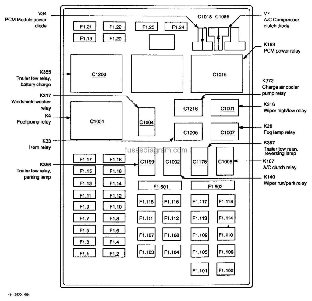
Assignment of the fuses (2002).
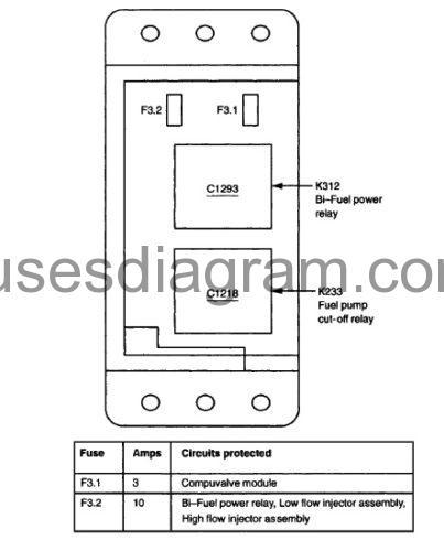
| Fuse | Amps | Circuits protected |
|---|---|---|
| F1.1 | 20 | Power point (19N236) |
| F1.2 | 30 | PCM power relay |
| F1.3 | 30 | Main Sight switch (11654), Headlamp relay, Multifunction switch |
| F1.4 | 15 | not used |
| F1.5 | 20 | Trailer low relay, parking lamp, Trailer tow relay, reversing lamp |
| F1.6 | 1S | Main light switch {11654), Park lamp relay |
| F1.7 | 20 | Horn relay |
| F1.8 | 15 | Door lock switch, driver side (14028), Door lock switch, passenger side (14028), Central Security Module (15604) |
| F1.9 | 15 | Daytime running lamps resistor, Fog lamp relay |
| F1.10 | 20 | Fuel pump relay |
| F1.11 | 20 | Generator |
| F1.12 | 20 | Power point, rear (19G247) |
| F1.13 | 15 | A/С clutch relay |
| F1.14 | – | not used |
| F1.15 | 10 | Running board lamp, left front, Running board lamp, left rear, Running board lamp, right front, Running board lamp, right rear |
| F1.16 | – | not used |
| F1.17 | – | not used |
| F1.18 | 15 | Mass Air Flow (MAF) sensor (12B579), Powertrain Control Module (PCM) (12A650), Injector 1 (9F593), Injector 2 (9F593), Injector 3 (9F593), Injector 4 (9F593), Injector 5 (9F593), Injector 6 (9F593), Injector 7 (9F593), injector 8 (9F593), Idle air control valve (IAC) (9F715), Fuel pump relay, Fuel pump cutoff relay |
| F1.19 | 10 | Trailer tow connector (15A416) |
| F1.20 | 10 | Trailer low connector (15A416) |
| F1.21 | – | not used |
| F1.22 | – | not used |
| F1.23 | 15 | Evaporative emission (EVAP) canister vent valve (9F945), EVAP canister purge valve, Heated Oxygen Sensor (H02S) #21 (9G444), Heated Oxygen Sensor (H02S) #11 (9G444), A/С clutch relay, Heated Oxygen Sensor (H02S) #22 (9F472), Heated Oxygen Sensor (H02S) #12 (9F472), Automatic transmission module (7G422), Camshaft position sensor (6B286), Intake Manifold Runner Control (IMRC) module, Bi-Fuel power relay |
| F1.24 | – | not used |
| F1.101 | 30 | Trailer tow relay, battery charge |
| F1.102 | 50 | ABS control module (2C219) |
| F1.103 | 50 | Central Junction Box (CJB) (14A068) |
| F1.104 | 30 | Transfer case relay module, Transfer case electric clutch relay, Mechanical Shift On the Fty (MSOF) relay |
| F1.105 | 40 | Blower motor relay |
| F1.106 | 20 | Charge air cooler pump relay |
| F1.107 | – | not used |
| F1.108 | 30 | Trailer tow connector (15A416) |
| F1.109 | – | not used |
| F1.110 | 30 | Accessory delay relay |
| F1.111 | 40 | Ignition switch (11572) |
| F1.112 | 30 | Adjustable pedal switch, Power seat switch, left |
| F1 .113 | 40 | Ignition switch (11572) |
| F1.114 | – | not used |
| F1.115 | 20 | Door lock switch, driver side (14028), Door lock switch, passenger side (14028), Central Security Module (15604) |
| F1.116 | – | not used |
| F1.117 | – | not used |
| F1.11B | 30 | Heated seat module, passenger side front, Heated seat module, driver side front |
| F1.601 C.B. | 30 | Accessory delay relay |
| F1.602 C.B. | – | not used |
Fuse box diagram (2003 model year).
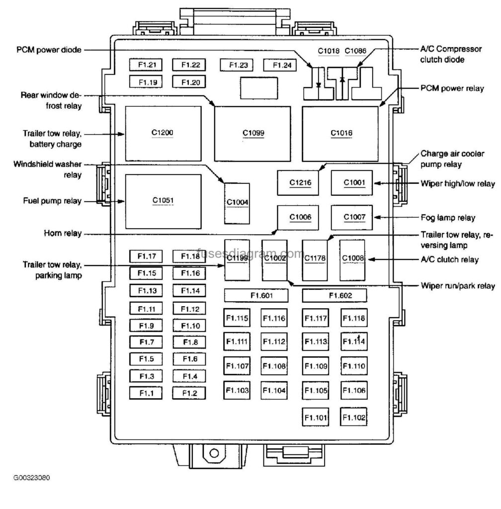
Assignment of the fuses (2003).
| Fuse | Amps | Circuits protected |
|---|---|---|
| F1.1 | 20 | Power point (19N236) |
| F1.2 | 30 | PCM power relay |
| F1.3 | 30 | Main light switch (11654), Headlamp relay, Multifunction switch |
| F1.4 | 20 | Power point, consols (19N236) |
| F1.5 | 20 | Trailer tow relay, parking lamp, Trailer tow relay, reversing lamp |
| F1.6 | 15 | Main light switch (11654), Park lamp relay |
| F1.7 | 20 | Horn relay |
| F1.8 | 15 | Centra! security module |
| F1.9 | 15 | Daytime running lamps resistor, Fog lamp relay |
| F1.10 | 20 | Fuel pump relay |
| F1. 11 | 20 | Generator |
| F1.12 | 20 | Power point, rear (19G247) |
| Fl.13 | 15 | A/С clutch relay |
| F1.14 | – | not used |
| F1.15 | 10 | Running board lamp, left front, Running board lamp, left rear, Running board lamp, right front, Running board Samp, right rear |
| F1.16 | 15 | Alternative Fuel Control Module (AFCM), Alternative fuel indicator switch, Fuel injectors |
| F1.17 | 2 | Brake pressure switch (2B264) |
| F1.18 | 15 | Mass Air Flow (MAF) sensor (12B579). Powertrain Control Module (PCM) (12A650), Fuel injector 1 (9F593), Fuel injector 2 (9F593), Fuel injector 3 (9F593), Fuel injector 4 (9F593), Fuel injectors (SF593), Fuel injector 6 (9F593), Fuel injector 7 (9F5S3), Fuel injector 8 (9F593), Idle Air Control (SAC) valve (9F715), Fuel pump relay, Fuel pump cutoff relay |
| F1.19 | 10 | Trai ler tow connector (15A418) |
| F1.20 | 10 | Trailer tow connector (15A416) |
| F1.21 | – | not used |
| F1.22 | – | not used |
| F1.23 | 15 | Evaporative emission (EVAP) canister vent valve (9F945), EVAP canister purge valve, Heated Oxygen Sensor (H02S) #21 (9F472), Heated Oxygen Sensor (H02S) #11 (9F472), A/С clutch relay, Heated Oxygen Sensor (H02S) #22 (9G444), Heated Oxygen Sensor (H02S) #12 (9G444), Automatic transmission module (7G422), Camshaft position sensor (6B288), Intake Manifold Runner Control (IMRC) module, Bi-Fuei power relay |
| F1.24 | – | not used |
| F1.101 | 30 | Trailer tow relay, battery charge |
| F1.102 | 50 | ABS control module (2C219) |
| F1.103 | 50 | Central Junction Box (CJB) (14AQ68) |
| F1.104 | 30 | Transfer case relay module, Transfer case electric clutch relay, Mechanical Shift On the Fiy (MSOF) relay |
| F1.105 | 40 | Blower motor relay |
| F1.106 | 20 | Charge air cooler pump relay |
| F1.107 | – | not used |
| F1.108 | 30 | Trailer tow connector (15A416) |
| F1.109 | – | not used |
| F1.110 | 30 | Accessory delay relay |
| F1.111 | 40 | Ignition switch (11572) |
| F1.112 | 30 | Adjustable pedal switch, Power seal switch, left |
| F1.113 | 40 | Ignition switch (11572) |
| F1.114 | – | not used |
| F1. 115 | 20 | Central security module |
| F1.116 | 40 | Rear window defrost relay |
| F1.117 | 40 | audio |
| F1.118 | 30 | Heated seat module, passenger side front. Heated seat module, driver side front (14C724) |
| F1.601 С.B. | 30 | Accessory delay relay |
| F1.802 C.B. | – | not used |
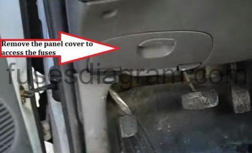
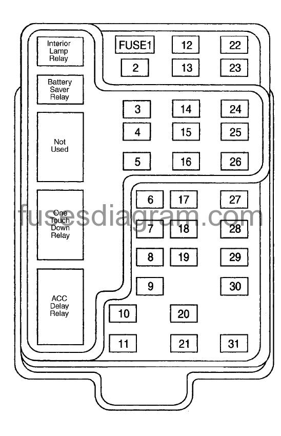
Passenger compartment fuse panel Ford F150 1997-2003.
The fuse panel is located below and to the left of the steering wheel by the brake pedal. Remove the panel cover to access the fuses. To remove a fuse use the fuse puller tool provided on the fuse panel cover.
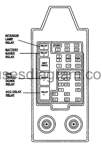
Assignment of the fuses (1997-1998).
| Fuse Position | Amps | Circuits Protected |
|---|---|---|
| 1 | 15 | Flasher Relay |
| 2 | 5 | instrument Cluster |
| 3 | 25 | Cigar lighter |
| 4 | 5 | Park Lamp Relay, Headlamp Relay, Autolamp Module, Remote Anti-Theft Personality (RAP) Module, Power Mirror Switch |
| 5 | 15 | *Transmission Range (TR) Sensor (NT), **Digital Transmission Range (DTR) Senor (A/T), Backup Lamp Switch (M/T), Daytime Running Lamps (DRL) Module, Speed Control Servo/Amplifier Assembly, Heater-A/C Control Assembly, Blend Door Actuator |
| 8 | 5 | Shift Lock Actuator, Generic Electronic Module (GEM), Rear Air Suspension (RAS) Module |
| 7 | – | NOT USED |
| 8 | 5 | Radio, Main Light Switch, Remote Anti-Theft Personality (RAP) Module |
| 9 | – | NOT USED |
| 10 | – | NOT USED |
| 11 | 30 | Washer Pump Relay, Wiper Run/Park Relay, Wiper Hi/LO Relay. Windshield Wiper Motor |
| 12 | 5 | Data Link Connector (DLC) |
| 13 | 15 | Rear Anti-Lock Brake System (RABS) Module, Brake On/Off (BOO) Switch, Brake Pressure Switch |
| 14 | 15 | Battery Saver Relay, Interior Lamp Relay |
| 15 | 5 | Generic Electronic Module (GEM) |
| 16 | 20 | Instrument Cluster (W/O DRL), Daytime Running Lamps (DRL) Module, Hi-Beam Headlamps (Power supplied through Multi-Function Switch) |
| 17 | – | NOT USED |
| 18 | 5 | Park Lamp Relay, Trailer Electronic Brake Controller, Main Light Switch, Trailer Tow Run Relay, Front Park/Turn Lamps, License Lamps, Slop/Park/Turn Lamps, Tail/Side Marker Lamps (Power supplied through Main Light Switch) |
| 19 | 10 | instrument Cluster, Air Bag Diagnostic Monitor |
| 20 | 5 | Powertrain Control Module (PCM), Generic Electronic Module (GEM)/Central Timer Module (CTM) |
| 21 | 15 | Clutch Pedal Position (CPP) Switch (W/O RAP), Starter Interrupt Relay (W/RAP) |
| 22 | 10 | Air Bag Diagnostic Monitor, Passive De-Activation (PAD) Module |
| 23 | 10 | Trailer Tow Battery Charge Relay, 4X4 Hub Solenoid, 4X2 Hub Solenoid, Basher Relay, Shift on the Fly Relay |
| 24 | 10 | Slower Relay |
| 25 | 5 | 4 Wheel Anti-Lock Brake System (4WABS) Module, 4WABS Relay |
| 26 | 10 | Daytime Running Lamps (DRL) Module, Right Headlamp |
| 27 | 5 | Main Light Switch, Fog Lamp Relay |
| 28 | 10 | Left Headlamp |
| 29 | 5 | Autolamp Module, Instrument Cluster, Transmission Control Switch (TCS), Brake Warning Resistor/Diode Assembly (W/RABS) |
| 30 | 30 | Radio Noise Capacitor, Ignition Coil, PCM Power Diode |
| 31 | – | NOT USED |
Assignment of the fuses (1999).
| Fuse/Relay Location | Fuse Amp Rating | Description |
|---|---|---|
| 1 | 15A | Audio |
| 2 | 5A | Powertrain Control Module (PCM), Cluster |
| 3 | 20A | Cigar Lighter, OBD-II Scan Tool Connector |
| 4 | 15A | Autolamp Module, Remote Entry Module, Mirrors |
| 5 | 15A | AC Clutch Relay, Speed Control Module, Reverse Lamp, Climate Mode Switch, Daytime Running Lamp Relay |
| 6 | 5A | Cluster, Brake Shift Interlock Solenoid, Rear Air Suspension Module, GEM Module |
| 7 | — | Not Used |
| 8 | 5A | Radio, Remote Entry Module, GEM Module |
| 9 | __ | Not Used |
| 10 | Not Used | |
| 11 | 30A | Front Washer Pump Relay, Wiper Run/Park Relay, Wiper Hi/LO Relay, Windshield Wiper Motor |
| 12 | Not Used | |
| 13 | 20A | Stop Lamp Switch (Lamps), Turn/Hazard Flasher, Speed Control Module |
| 14 | 15A | Battery Saver Relay, Interior Lamp Relay, Accessory Delay Relay (Power Windows) |
| 15 | 5A | Stop Lamp Switch, (Speed Control, Brake Shift Interlock, ABS, PCM Module Inputs), GEM Module, RABS Test Connector |
| 16 | 20A | Headlamps (Hi Beams), Cluster (Hi Beam Indicator) |
| 17 | Not Used | |
| 18 | 5A | Instrument Illumination (Dimmer Switch Power) |
| 19 | Not Used | |
| 20 | 5A | Audio, GEM Module, Powertrain Control Module (PCM), |
| 21 | 15A | Starter Relay, Clutch Switch, Fuse 20 |
| 22 | 10 A | Air Bag Module, Passenger Airbag Deactivation Module |
| 23 | 10A | Trailer Tow Battery Charge Relay, Turn/Hazard Flasher, 4×4 Solenoids, 4×4 Relays |
| 24 | 10A | Climate Mode Switch (Blower Relay) |
| 25 | 5A | 4 Wheel Anti-Lock Brake System (4WABS) Module |
| 26 | 10A | Right Side Low Beam Headlamp |
| 27 | 5A | Foglamp Relay and Foglamp Indicator |
| 28 | 10A | Left Side Low Beam Headlamp |
| 29 | 5A | Autolamp Module, Transmission Overdrive Control Switch |
| 30 | 30A | Passive Anti Theft Transceiver, Cluster, Ignition Coils, Powertrain Control Module Relay |
| 31 | — | Not Used |
| Relay 1 | — | Interior Lamp Relay |
| Relay 2 | — | Battery Saver Relay |
| Relay 4 | — | One Touch Down Window Relay |
| Relay 5 | — | ACC Delay Relay |
Fuse box diagram Ford F150 2000-2001.
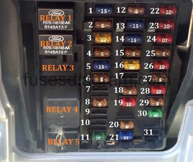
The fuses are coded as follows (2000-2001).
| Num | Amps | Description |
|---|---|---|
| 1 | 15A | Audio |
| 2 | 5A | Powertrain Control Module (PCM), Cluster |
| 3 | 20A | Cigar Lighter, Data Link Connector |
| 4 | 5A | Exterior Rear View Mirror Switch, Mirror turn Signal Relays |
| 5 | 15A | Speed Control Module, Reverse Lamp, Climate Mode Switch, Daytime Running Lamp Relay, Digital Transmission Range (DTR) Sensor |
| 6 | 5A | Cluster, Brake Shift Interlock Solenoid, GEM Module |
| 7 | — | Not Used |
| 8 | 5A | Radio, Remote Entry Module, GEM Module, In-vehicle entertainment system (SuperCrew only) |
| 9 | — | Not Used |
| 10 | — | Not Used |
| 11 | 30A | Front Washer Pump Relay, Wiper Run/Park Relay, Wiper Hi/LO Relay, Windshield Wiper Motor |
| 12 | — | Not Used |
| 13 | 20A | Stop Lamp Switch (Lamps), Turn/Hazard Flasher |
| 14 | 15A | Battery Saver Relay, Interior Lamp Relay |
| 15 | 5A | Stop Lamp Switch, (Speed Control, Brake Shift Interlock), GEM Module, RABS Module |
| 16 | 20A | Headlamps (Hi Beams), Cluster (Hi Beam Indicator) |
| 17 | — | Not Used |
| 18 | 5A | Instrument Illumination (Dimmer Switch Power) |
| 19 | — | Not Used |
| 20 | 5A | Audio, GEM Module, Powertrain Control Module (PCM), Transmission Range Sensor |
| 21 | 15A | Digital Transmission Range (DTR) Sensor, Clutch Switch, Starter Relay, I/P fuse 20 |
| 22 | 10A | Air Bag Module, Passenger Airbag Deactivation Module |
| 23 | 10A | Trailer Tow Battery Charge Relay, Turn/Hazard Flasher, 4×4 Solenoids, 4×4 Relays, Overhead Console, 4 Wheel Anti-Lock Brake System (4WABS) Module, EC Mirror, Heated Seats |
| 24 | 10A | Function Selector Switch Assembly |
| 25 | — | Not Used |
| 26 | 10A | Right Side Low Beam Headlamp |
| 27 | 5A | Fog lamp Relay and Fog lamp Indicator, Main Light Switch (upstream) |
| 28 | 10A | Left Side Low Beam Headlamp |
| 29 | 5A | Auto lamp Module, Transmission Overdrive Control Switch, Central Security Module,Belt Minder |
| 30 | 30A | Passive Anti-Theft Transceiver, Cluster, Ignition Coils, Powertrain Control Module Relay, Coil on Plugs, Radio Noise Capacitor, ECC Diode |
| 31 | — | Not Used |
| Relay 1 | — | Interior Lamp Relay |
| Relay 2 | — | Battery Saver Relay |
| Relay 3 | — | Not Used |
| Relay 4 | — | One Touch Down Window Relay |
| Relay 5 | — | ACC Delay Relay |
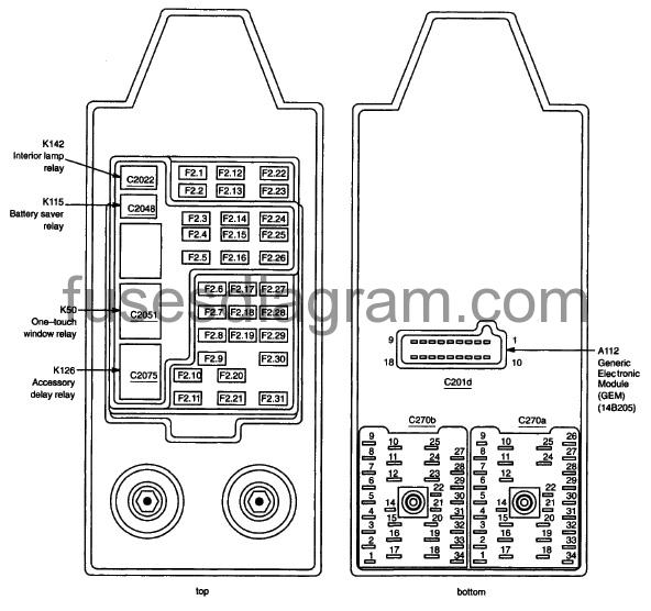
Assignment of the fuses (2002-2003).
| Fuse | Amps | Circuits protected |
|---|---|---|
| F2.1 | 15 | In-line fuse 1, Radio (19806), CD changer (18D806) |
| F2.2 | 5 | Instalment cluster, Powertrain Control Module (PCM) (12A650), Electronic Automatic Temperature Control (EATC) module (19980), Natural Gas Vehicle (NGV) timer |
| F2.3 | 20 | Data Link Connector (DLC) (14489), Cigar lighter, front (15055) |
| F2.4 | 5 | Mirror turn signal relay, left, Mirror turn signal relay, right, Exterior rear view mirror switch (17B676) |
| F2.5 | 15 | Digital Transmission Range (DTR) sensor (7F293), Reversing lamps switch, Speed control servo (9C735), Function selector switch assembly, Temperature biend door actuator (19E616). Daytime Running Lamps (DRL) relay 2 |
| F2.6 | 5 | Generic Electronic Module (GEM) (148205), Brake shift interlock (3Z719), Instalment cluster |
| F2.7 | – | not used |
| F2.8 | 5 | Generic Electronic Module (GEM) (14B205), Remote Anti-theft Person alty (HAP) module. In-line luse 2, Radio (18806) |
| F2.9 | – | not used |
| F2.10 | – | not used |
| F2.11 | 30 | Windshield washer relay, Wiper run/park relay, Wiper high/low relay, Windshield wiper motor (17508) |
| F2.12 | – | not used |
| F2.13 | 20 | indicator flasher relay (13350), Brake pedal position switch (13480) |
| F2.14 | 15 | Battery saver relay, Interior lamp relay |
| F2.15 | 5 | Generic Electronic Module (GEM) (148205), Brake pressure switch (2B264), Brake pedal position switch (13480) |
| F2.16 | 20 | Instrument duster, Headlamp, left (1300B), Headlamp, right (13008) |
| F2.17 | – | not used |
| F2.18 | 5 | Main tight switch (11654) |
| F2.20 | 5 | Powertrain Control Module (PCM) (12A650), Generic Electronic Module (GEM) (148205), Radio (18806) |
| F2.21 | 15 | Clutch pedal position switch, Clutch triple function switch jumper, Centra! Junction Bo* (CJB) (14A068), Digital Transmission Range (DTR) sensor (7F293) |
| F2.22 | 10 | Restraints control module (14B321), Passenger Air bag Deactivation (PAD) switch |
| F2.23 | 10 | Trailer tow relay, battery charge, 4×2 center axle disconnect solenoid, 4×4 center axle disconnect solenoid, Indicator flasher relay (13350), Transfer case electric clutch relay. Mechanical Shift On the Fly (MSOF) relay ABS control module (2C219), Heated seat module, driver side front, Seat heater switch, driver side, Heated seat module, passenger side front, Seat heater switch, passenger side, Overhead console, Elec trochromatic inside mirror unit (17700) |
| F2.24 | 10 | Function selector swilcti assembly, Blower motor relay, Electronic Automatic Temperature Control (EATC) module (19900) |
| F2.25 | – | not used |
| F2.26 | 10A | Headlamp, right (13008) |
| F2.27 | 5 | Main light switch (11654) |
| F2.28 | 10 | Headlamp, left (13008) |
| F2.29 | 5 | Transmission control switch, Autolamp sensor (14A597), Central Security Module (15604), Belt minder module |
| F2.30 | 30 | PCM Module power diode, Ignition transformer capacitor 1 (18801), Ignition coil, Natural Gas Vehicle (NGV) timer, Instrument cluster, Pas sive anti-theft transceiver module (15607) |
| F2.31 | – | not used |
Relay box 1 Ford F150 1999-2003.
Relay box 1 is located behind left side of instrument panel.
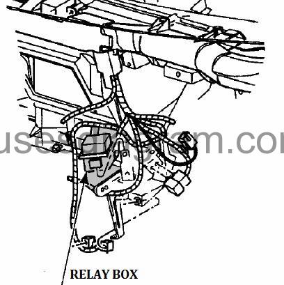
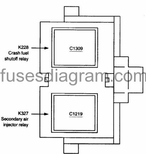
identifying relay box 1.
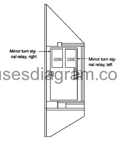
Relay box 2 Ford F150 1999-2003.
Relay box 2 is located behind right side of instrument panel.
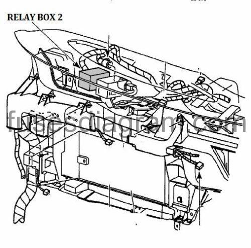
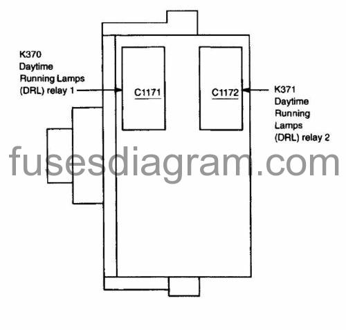
identifying relay box 2.
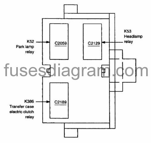
Relay box 3 Ford F150 1999-2003.
Relay box 3 is located behind right side of instrument panel.
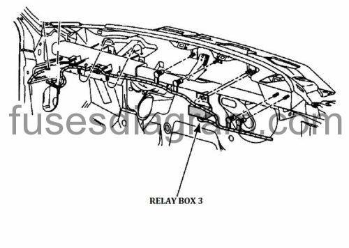
identifying relay box 3.
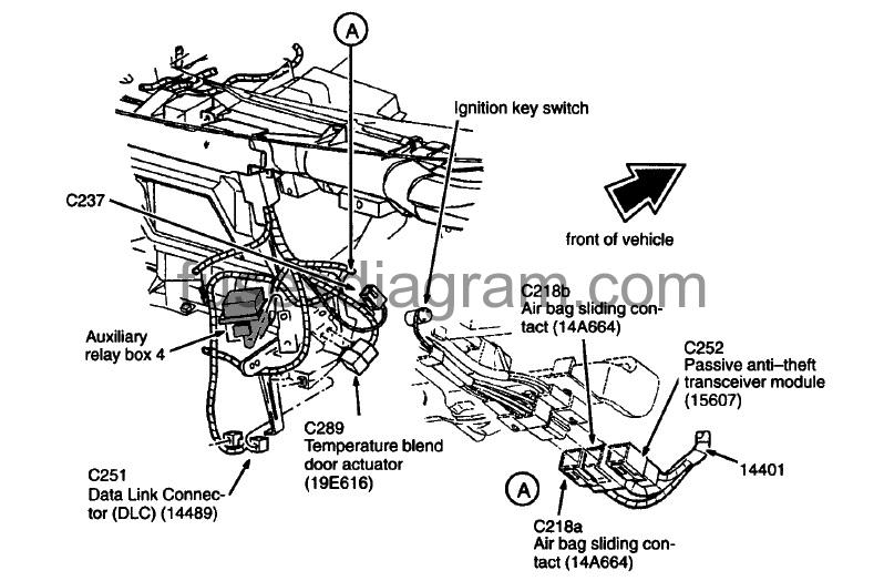
Relay box 4 Ford F150 1999-2003.
Auxiliary relay box 4 is located behind left side of instrument panel.
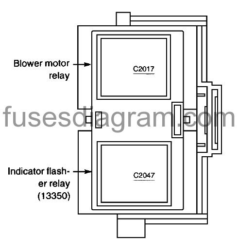
Relay box 5 Ford F150 1999-2003.
Auxiliary relay box 5 is located behind right side of instrument panel.

Bi-fuel relay module is located in left rear of engine compartment.
Primary battery fuses (megafuses) F150 1997-1998.
Primary battery fuses are located under the PRIMARY BATTERY FUSE cover next to starter relay. Ford recommends that megafuses only be serviced by a qualified service technician.
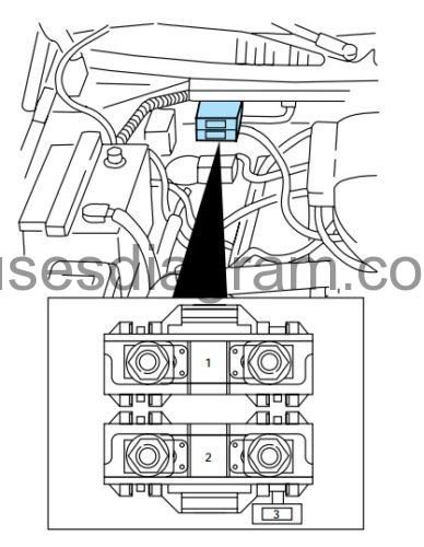
1 – (175A) Power network box
2 – (175A) Alternator
3 – (20A) Alternator field
Engine minifuse panel F150 1997-1998.
The minifuse panel is located behind the power distribution box.
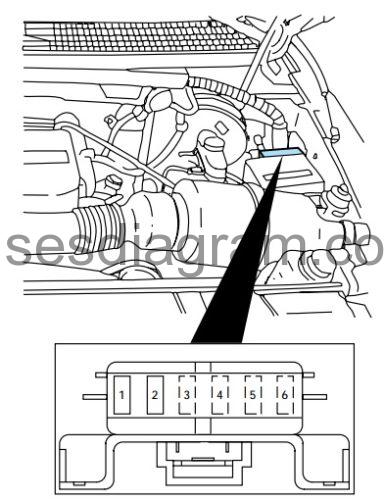
| Location | Amps | Description |
|---|---|---|
| 1 | 5 | Powertrain control module (PCM) |
| 2 | 20 | Trailer tow stop/turn lamps |
| 3 | Not used | |
| 4 | Not used | |
| 5 | Not used | |
| 6 | Not used |