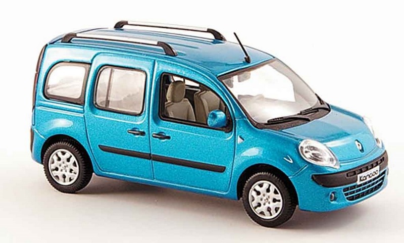
In this article you will learn about the fuses of second generation Renault Kangoo cars (K61, F61), which were produced in 2008, 2009, 2010, 2011, 2012, 2013, 2014, 2015, 2016, 2017, 2018, 2019, 2020, 2021, with petrol (1.6) and diesel (1.5) engines. A facelifted version of both the van and the passenger versions was available from the beginning of 2013. You will also know where the fuses are, in particular the fuel pump fuse, cigarette lighter fuses, alarm fuses, stove (heating), low beam headlights, windshield washer, dimensions, central locking, fan, generator…
| The cigarette lighter fuse is located under number F2/10A – Fuse box in the passenger compartment. |
Content:
Fuse and relay box in the passenger compartment.
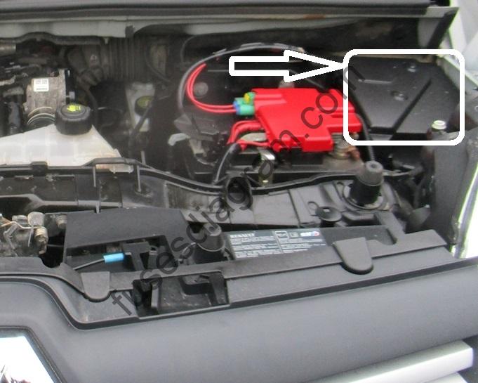
Fuse box in engine compartment.
Additional relays in the passenger compartment.
Fuse and relay box in the passenger compartment.
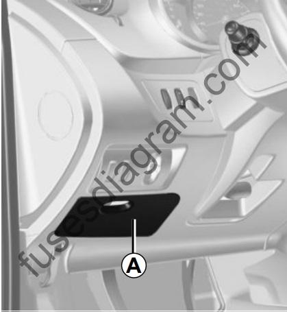
To access the fuses, unscrew cover A.
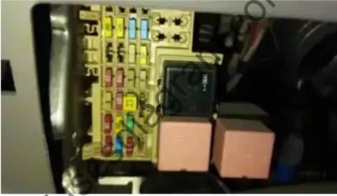
fuse layout diagram in the block (2008-2012).
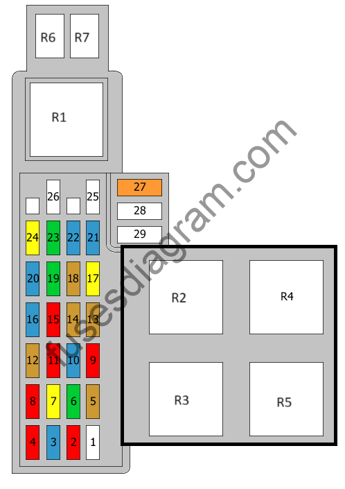
Fuse assignment.
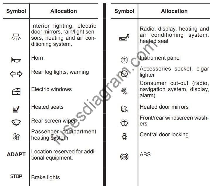
| № | Amp | Affectation |
|---|---|---|
| 1 | Not used | |
| 2 | 10A | Cigarette lighter or accessory socket |
| 3 | 15A | Accessory relay 2 Radio Multifunction display Seat relay Stop light relay Heater Air conditioner control unit |
| 4 | 10A | Rear accessory socket |
| 5 | 5A | Dashboard |
| 6 | 30A | Via driver’s side door module (DDM) and passenger’s side door (PDM): central locking |
| 7 | 20A | Interior computer Fog lights Hazard warning light |
| 8 | 10A | Electric mirrors |
| 9 | 10A | Accessory relay 2 Motor running relay |
| 10 | 15A | Data bus (CAN) Alarm system Video system Radio Multifunction display |
| eleven | 10A | Air conditioning control unit Accessory relay 1 Interior computer Additional fuse Front courtesy lamp(s) Luggage compartment lighting Stop light switch Interior lighting Rain sensor Light sensor Electric mirror Data bus (CAN) ) |
| 12 | 5A | Cabin computer Or Not used |
| 13 | 5A | Rain sensor Light sensor Front courtesy lamp(s) Interior lighting |
| 14 | 5A | Air conditioning control unit Power window relay Power window control unit Rear power window closing Power window child safety relay |
| 15 | 10A | ABS cabin computer |
| 16 | 15A | Cabin computer ABS Stop light switch High level stop light Rear lighting Automatic transmission control unit |
| 17 | 20A | Steering column switches Wash pumps, front and rear |
| 18 | 5A | Cabin computer Snorter |
| 19 | 30A | Power window relay |
| 20 | 15A | Front heated seats Seat relay Heated seat control Engine running relay |
| 21 | 15A | Steering column switches Horn Diagnostic socket |
| 22 | 15A | Rear wiper motor Windshield wiper motor Cabin computer |
| 23 | 30A | Fan (20A is also used) |
| 24 | 20A | Fan |
| 25 | Not used | |
| 26 | Not used | |
| 27 | 40A | Power window relay Cabin computer Front power windows |
| 28 | Not used | |
| 29 | Not used | |
| R1 | Accessory relay 1 | |
| R2 | Additional heating relay 1 | |
| R3 | Additional heating relay 2 | |
| R4 | Power window relay Control unit | |
| R5 | Power window relay | |
| R6 | Motor On Relay | |
| R7 | Accessory relay 2 |
fuse layout diagram in the block (2012-2021).
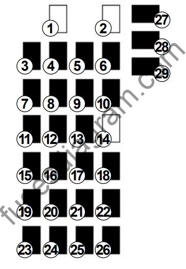
Fuse assignment.
| Number | Allocation |
|---|---|
| 1 | Fuel pump |
| 2 | Not used |
| 3 | Passenger compartment engine cooling fan |
| 4 | Passenger compartment engine cooling fan |
| 5 | Rear windscreen wiper |
| 6 | Horn, diagnostic socket |
| 7 | Heated seats |
| 8 | Electric rear windows |
| 9 | Passenger compartment ECU |
| 10 | Windscreen washer |
| 11 | Brake lights |
| 12 | Passenger compartment unit, ABS, ESP |
| 13 | Electric windows, child safety, heating and air conditioning system, ECO mode |
| 14 | Not used |
| 15 | Starter |
| 16 | Brake lights, additional equipment, navigation, ABS, ESP, boot light, tyre pressure warning light, interior lights, rain and light sensor |
| 17 | Radio, navigation system, display, alarm |
| 18 | Additional equipment |
| 19 | Heated door mirrors |
| 20 | Hazard lights, rear fog lights |
| 21 22 | Central locking of opening elements Instrument panel |
| 23 | Rear accessories socket |
| 24 | ESC, radio, heating and air conditioning system, heated seats, stop lights |
| 25 | Front accessories socket Cigarette lighter fuse |
| 26 | Towbar |
| 27 | Electric front windows |
| 28 | Rear-view mirror control |
| 29 | De-icing the rear screen and rear view mirror |
Fuse box in engine compartment.
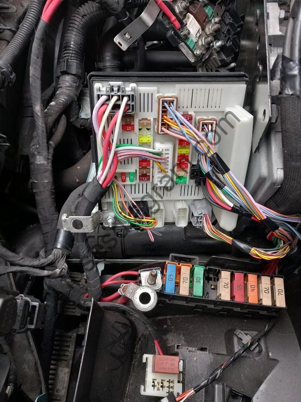
fuse box diagram.
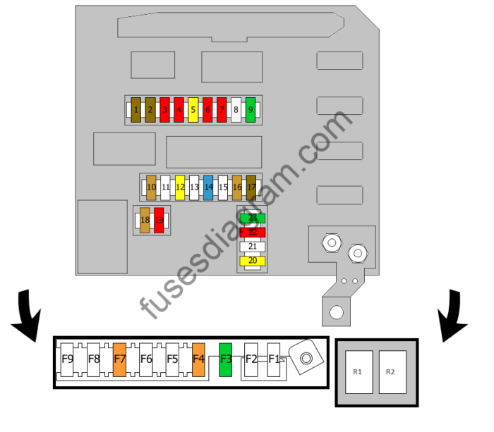
Fuse assignment.
| № | Amp | Circuits Protection |
|---|---|---|
| 1 | 7.5A | Side light, right |
| 2 | 7.5A | Side light, left Side lights, rear right License plate lighting Cigarette lighter Accessory socket Air conditioning heating control Traction control switch Speed limiter |
| 3 | 10A | Headlight adjustment control unit Headlight range control, right side Light beam managed by the right dimmer |
| 4 | 10A | Projector adjustment Light beam managed by the left dimmer |
| 5 | 20A | Front fog light(s) |
| 6 | 10A | Left main beam |
| 7 | 10A | Right main beam |
| 8 | 25A | ABS Or ESP Control Unit |
| 9 | 30A | Windshield wiper motor |
| 10 | 5A | Power steering + After ignition charge |
| eleven | Not used | |
| 12 | 20A | Automatic transmission control unit |
| 13 | Not used | |
| 14 | 15A | Flow meter Camshaft sensor Fuel Exhaust gas recirculation (EGR) Injection timing control valve Turbo control solenoid |
| 15 | Not used | |
| 16 | 5A | Automatic transmission control unit |
| 17 | 7.5A | Passenger compartment + After ignition charge Cruise control Speed limiter |
| 18 | 5A | + After ignition charge Water sensor Engine wiring cover Fuel injection computer |
| 19 | 10A | + After charge ignition Or Reversing light switch |
| 20 | 20A | Fuel injection computer |
| 21 | Not used | |
| 22 | 10A | Air conditioner compressor clutch |
| 23 | 30A | Heated rear window Mirrors |
| F1 | 60A | Refrigerant Liquid Heater |
| F2 | 70A | Glow plug control module Coolant heater |
| F3 | 30A | Diesel Fuel Heater Engine Control Unit Relay |
| F4 | 40A | Power Window Motor Or Selespeed Gearbox Relay (30A is also used) |
| F5 | 70A | Fuse and relay box in engine compartment |
| F6 | 50A | ABS computer |
| F7 | 40A | Additional heating relay 1 |
| F8 | 70A | Fuse and relay box in engine compartment |
| F9 | 70A | Additional heating relay 2 |
| R1 | Not used | |
| R2 | Diesel Fuel Heating |
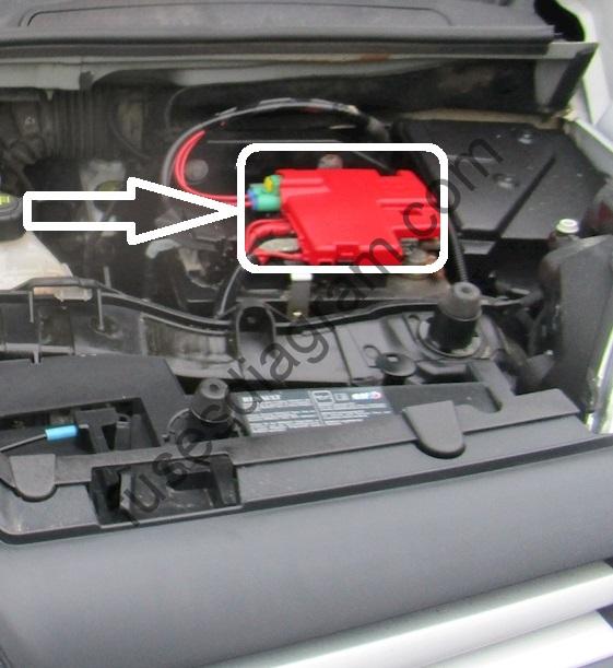
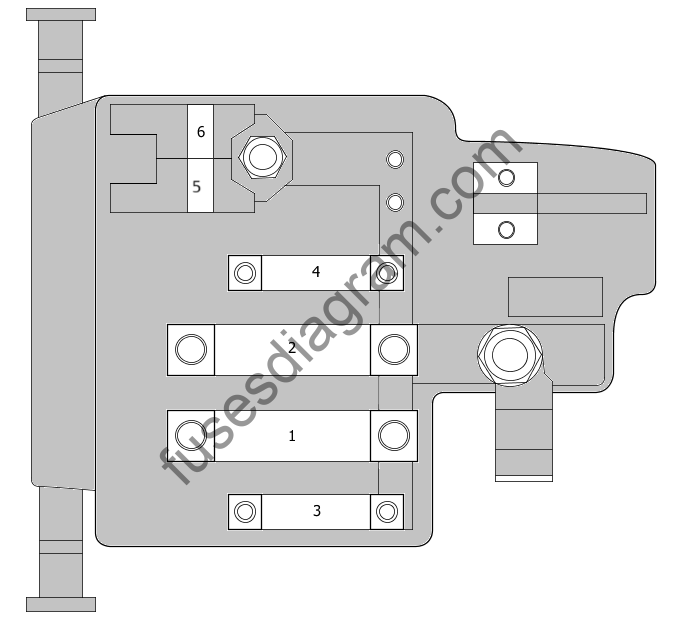
| № | Amp | Circuits Protection |
|---|---|---|
| 1 | 175A | Fuse box in engine compartment Alternator Power supply to fuse box |
| 2 | 500A 200A | Battery Starter |
| 3 | 40A | Battery Fuse box in engine compartment |
| 4 | 40A | Battery Starter Battery supply Additional cooling fan Fuse box in engine compartment |
| 5 | 70A | Power steering control unit |
| 6 | 40A | Chassis Control Unit (UCH) Battery power Fuse and relay box in engine compartment |
Additional relays in the passenger compartment.
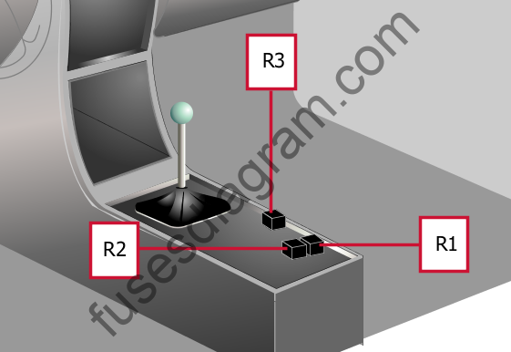
Relay R1
Driver’s electric seat power supply
Relay R2
Stop lights
Relay R3
Child safety relay for electric windows

