For the Volkswagen Crafter 2006, 2007, 2008, 2009, 2010, 2011, 2012, 2013, 2014, 2015, 2016, 2017 model year.
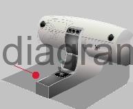
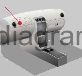
Fuse box in passenger compartment (under driver’s seat).
fuse box diagram (04/2009-04/2011)
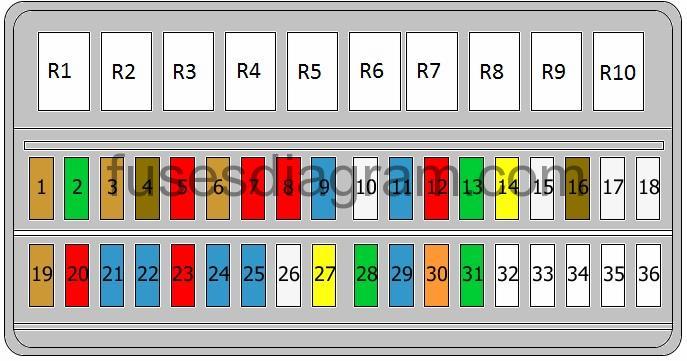
legend.
| Fuse | Amps | Circuits Protected |
|---|---|---|
| 1 | 5A | Driver’s power window Heated rear windscreen relay |
| 2 | 30A | Windscreen wiper(s) motor |
| 3 | 5A | Clock Park/neutral position switch Information display Rear-view camera system |
| 4 | 7.5A | Trailer detection control unit Heated rear windscreen relay Or Trailer detection control unit Working speed control switch Power take-off warning switch Tachograph |
| 5 | 10A | Selector lever Automatic transmission control unit |
| 6 | 5A | Crankcase breather heater |
| 7 | 10A | Fuel filter heater |
| 8 | 10A | Tilting mechanism switch Special equipment Connector(s) |
| 9 | 15A | Roof ventilator Siren relay |
| 10 | 25A | Vehicle data interface (VDI) |
| 11 | 15A | Special equipment |
| 12 | 10A | Special equipment |
| 13 | 30A | Special equipment Or Air-conditioning control unit (10A also used) |
| 14 | 20A | Trailer detection control unit Or Connector Trailer connector socket |
| 15 | 25A | Trailer detection control unit |
| 16 | 7.5A | Parking assistance control unit Tyre pressure monitor control unit |
| 17 | 25A | Special equipment |
| 18 | 25A | Special equipment |
| 19 | 5A | Control unit, roof electronics (25A also used) |
| 20 | 10A | Continued coolant circulation relay |
| 21 | 15A | Heated rear windscreen relay (30A also used) |
| 22 | 15A | Heated rear windscreen relay |
| 23 | 10A | 12V socket Or 12V socket Illumination, switch(es) (15A also used) |
| 24 | 15A | 12V socket |
| 25 | 15A | 12V socket |
| 26 | 25A | Additional heater control unit |
| 27 | 20A | Additional heater control unit (25A also used) |
| 28 | 30A | Air-conditioning control unit Or Gearbox hydraulic pump relay (40A also used) |
| 29 | 15A | Automatic transmission control unit |
| 30 | 40A | Gearbox hydraulic pump relay (30A also used) or not used |
| 31 | 30A | Fresh-air blower control unit Blower |
| 32 | Not used | |
| 33 | Not used | |
| 34 | 15A | Reductant control unit |
| 35 | 15A | Reductant control unit |
| 36 | Not used | |
| R1 | Special equipment | |
| R2 | Special equipment | |
| R3 | Interior light(s) relay Or Tipping mechanism relay Or Tailgate lift relay | |
| R4 | Headlight washer relay | |
| R5 | Rotating light relay | |
| R6 | Alarm relay | |
| R7 | Coolant pump relay | |
| R8 | Continued coolant circulation relay | |
| R9 | Siren relay | |
| R10 | Not used |
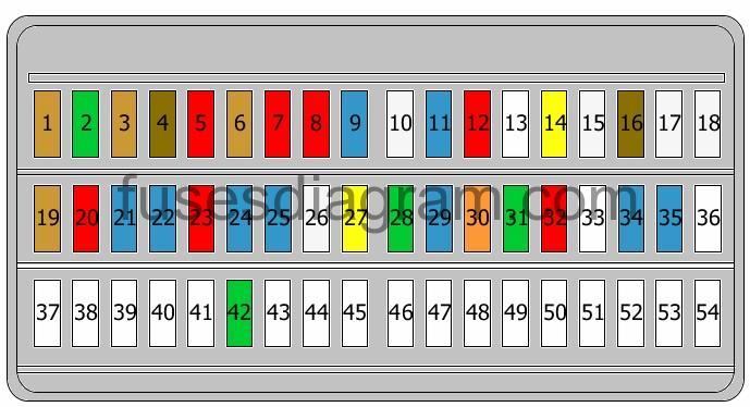
fuse box diagram (05/2011-).
| Fuse | Amps | Circuits Protected |
|---|---|---|
| 1 | 5A | Driver’s power window Heated rear windscreen relay |
| 2 | 30A | Windscreen wiper(s) motor |
| 3 | 5A | Clock Park/neutral position switch Information display Rear-view camera system |
| 4 | 7.5A | Trailer detection control unit Working speed control switch Power take-off warning switch Tachograph |
| 5 | 10A | Selector lever Automatic transmission control unit |
| 6 | 5A | Crankcase breather heater Battery regulation control unit |
| 7 | 10A | Fuel filter heater |
| 8 | 10A | Tilting mechanism switch Special equipment Connector(s) |
| 9 | 15A | Roof ventilator Siren relay |
| 10 | 25A | Vehicle data interface (VDI) |
| 11 | 15A | Special equipment |
| 12 | 10A | Special equipment |
| 13 | Not used | |
| 14 | 20A | Connector Trailer connector socket |
| 15 | 25A | Trailer detection control unit |
| 16 | 7.5A | Parking assistance control unit Tyre pressure monitor control unit |
| 17 | 25A | Special equipment |
| 18 | 25A | Special equipment |
| 19 | 5A | Control unit, roof electronics (25A also used) |
| 20 | 10A | Continued coolant circulation relay Illumination relay |
| 21 | 15A | Heated rear windscreen relay (30A also used) |
| 22 | 15A | Heated rear windscreen relay |
| 23 | 10A | 12V socket Illumination, switch(es) (15A also used) |
| 24 | 15A | 12V socket |
| 25 | 15A | 12V socket |
| 26 | 25A | Additional heater control unit |
| 27 | 20A | Additional heater control unit (25A also used) |
| 28 | 30A | Gearbox hydraulic pump relay (40A also used) |
| 29 | 15A | Automatic transmission control unit |
| 30 | 5A | Battery regulation control unit (30A also used) |
| 31 | 30A | Fresh-air blower control unit Blower |
| 32 | 10A | Battery monitor control unit |
| 33 | Not used | |
| 34 | 15A | Reductant control unit |
| 35 | 15A | Reductant control unit |
| 36 | Not used | |
| 37 | Not used | |
| 38 | Not used | |
| 39 | Not used | |
| 40 | Not used | |
| 41 | Not used | |
| 42 | 30A | Air-conditioning control unit |
| 43 | Not used | |
| 44 | Not used | |
| 45 | Not used | |
| 46 | Not used | |
| 47 | Not used | |
| 48 | Not used | |
| 49 | Not used | |
| 50 | Not used | |
| 51 | Not used | |
| 52 | Not used | |
| 53 | Not used | |
| 54 | Not used |
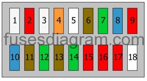
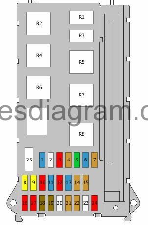
Fuse box №1 in passenger compartment.
fuse box layout.
| Fuse | Amps | Circuits Protected |
|---|---|---|
| 1 | 25A | Driver’s door control unit |
| 2 | 10A | Diagnostic connector |
| 3 | 25A | ABS control unit |
| 4 | 40A | ABS control unit |
| 5 | Not used | |
| 6 | 7,5A | Reductant control unit Reductant reversing valve Reductant pump or not used |
| 7 | 30A | Headlight washer pump |
| 8 | 15A | Alarm horn Alarm relay Or Alarm horn Alarm relay Rotating light and siren system control unit Rotating light(s) Siren relay |
| 9 | 10A | Special equipment or not used |
| 10 | 15A | Radio Radio and navigation unit |
| 11 | 7,5A | Mobile phone control unit Tachograph |
| 12 | 30A | Heater switch Blower relay Fresh-air blower control unit Blower |
| 13 | 7,5A | Clock Remote control receiver for the auxiliary coolant heater |
| 14 | 30A | Dash panel |
| 15 | 10A | Illumination, switch(es) or not used |
| 16 | 10A | Heater switch Air-conditioning control unit CD changer |
| 17 | 10A | Illumination, switch(es) |
| 18 | Not used |
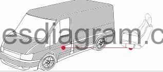
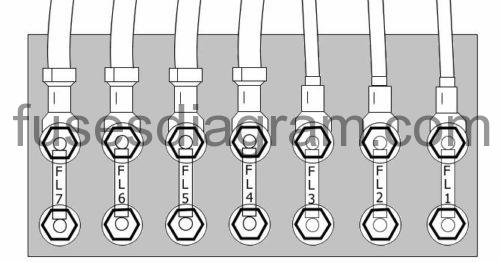
Fuse box №2 in passenger compartment (on battery).
| Fuse | Amps | Circuits Protected |
|---|---|---|
| FL1 | 80A | Glow plug control unit |
| FL2 | 40A | Radiator fan control unit Cooling fan (60A also used) (80A also used) or not used |
| FL3 | 80A | Power supply control unit Power supply relay Fuse and relay box No. 1 in passenger compartment, fuses 2, 3, 8 – 10, 16 |
| FL4 | 150A | Second battery Additional fuse in passenger compartment Or Second battery Additional fuse in passenger compartment Fuse and relay box No. 2 in passenger compartment, fuses 23 – 25 |
| FL5 | 150A | Terminal 15 voltage supply relay Horn relay Power supply control unit Fuse box No. 1 in passenger compartment Fuse and relay box No. 1 in passenger compartment, fuses 1, 4 – 7, 11 – 15, 17 – 23, 25 Terminal 15 relay 2 |
| FL6 | Heated windscreen Fuse and relay box No. 2 in passenger compartment Or Heated windscreen Fuse and relay box No. 2 in passenger compartment Additional fuse in passenger compartment | |
| FL7 | 150A | Additional heater |
Relay box in passenger compartment.
location.
relay box diagram (pre 04/2009).
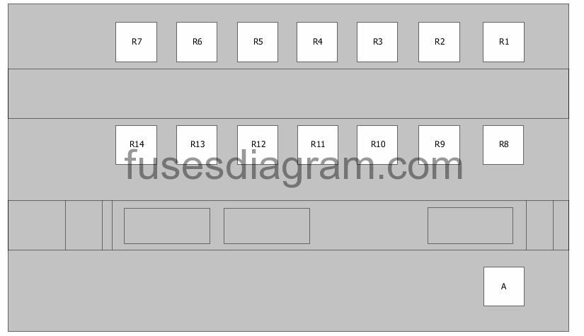
Relay R1 – Terminal 15 voltage supply relay
Relay R2 – Heated rear windscreen relay
Relay R3 – Terminal 15 voltage supply relay
Relay R4 – Not used
Relay R5 – Heated windscreen relay
Relay R6 – Heated rear windscreen relay
Relay R7 – Blower relay or not used
Relay R8 – Gearbox hydraulic pump relay or not used
Relay R9 – Not used
Relay R10 – Not used
Relay R11 – Not used
Relay R12 – Not used
Relay R13 – Not used
Relay R14 – Not used
Relay A – Battery isolation relay
relay box diagram (since 05/2009).
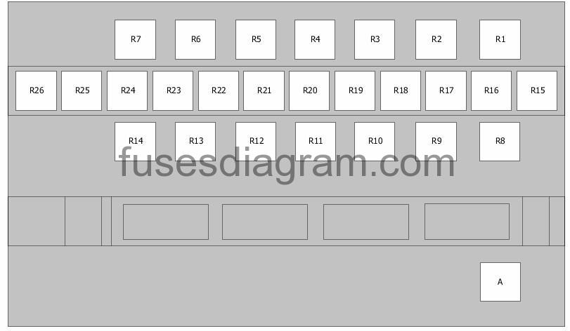
Relay R1 – Not used
Relay R2 – Terminal 15 relief relay
Relay R3 – Terminal 15, relief relay 3
Relay R4 – Gearbox hydraulic pump relay
Relay R5 – Heated rear windscreen relay
Relay R6 – Heated rear windscreen relay
Relay R7 – Terminal 15, relief relay 2
Relay R8 – Not used
Relay R9 – Heated windscreen relay
Relay R10 – Blower relay
Relay R11 – Not used
Relay R12 – Not used
Relay R13 – Not used
Relay R14 – Not used
Relay R15 – Special equipment or not used
Relay R16 – Special equipment or not used
Relay R17 – Tailgate lift relay or Interior light(s) relay or not used
Relay R18 – Headlight washer relay or not used
Relay R19 – Siren relay or Illumination relay or not used
Relay R20 – Alarm relay or not used
Relay R21 – Coolant pump relay or not used
Relay R22 – Continued coolant circulation relay or Illumination relay or not used
Relay R23 – Siren relay or not used
Relay R24 – Not used
Relay R25 – Not used
Relay R26 – Parking warning buzzer or not used
Relay A – Battery isolation relay
Fuse box in engine compartment Volkswagen Crafter.
| Fuse | Amps | Circuits Protected |
|---|---|---|
| 1 | 15A | Horn |
| 2 | 25A | Ignition lock Steering column lock control unit |
| 3 | 10A | Ignition lock Control unit with display in the dash panel insert Engine control unit |
| 4 | 5A | Light switch Dash panel |
| 5 | 30A | Windscreen wiper motor |
| 6 | 15A | Fuel pressure pump |
| 7 | 5A | Control unit, steering column electronics |
| 8 | 20A | Engine control unit |
| 9 | 20A | Fuse box No. 1 in passenger compartment, fuse 6 Or Fuse and relay box No. 2 in passenger compartment, fuses 34 – 36 or not used |
| 10 | 10A | Fuel pressure control solenoid Crankcase breather heater Mass airflow meter Reductant reversing valve Reductant pump Exhaust gas cooler solenoid Exhaust gas recirculation coolant pump |
| 11 | 15A | Terminal 15, relief relay 2 Fuse and relay box No. 2 in passenger compartment, fuses 1, 2 |
| 12 | 10A | Airbag control unit |
| 13 | 15A | Glovebox illumination switch Cigarette lighter |
| 14 | 5A | Light switch Control unit with display in the dash panel insert Diagnostic connector |
| 15 | 5A | Heater switch Headlight range control Left headlight range control motor Right headlight range control motor |
| 16 | 10A | Engine Start and Stop system switch Park/neutral position switch Oil level and temperature sensor Fuel pump relay Continued coolant circulation relay Glow plug control unit Terminal 50 voltage supply relay Turbo pressure control solenoid Coolant valve Fuel metering solenoid Exhaust gas cooler solenoid Heated oxygen sensor |
| 17 | 10A | Airbag control unit |
| 18 | 7,5A | Terminal 15 relief relay Or Terminal 15 relief relay Brake light switch Brake pedal switch |
| 19 | 7,5A | Power supply control unit |
| 20 | 25A | Power supply control unit |
| 21 | 5A | Mass airflow meter Engine control unit |
| 22 | 5A | Brake light switch Brake pedal switch Or Lateral acceleration sensor Longitudinal acceleration sensor ABS control unit |
| 23 | 25 | Starter Power supply control unit |
| 24 | 10A | |
| 25 | 25A | 12V socket |
| R1 | Horn relay | |
| R2 | Wiper switch | |
| R3 | Fuel pump relay | |
| R4 | Wiper switch | |
| R5 | Terminal 50 voltage supply relay | |
| R6 | Terminal 15 voltage supply relay | |
| R7 | Main relay | |
| R8 | Terminal 15 voltage supply relay |