For the Mitsubishi Lancer Evolution (CT) 2003, 2004, 2005, 2006, 2007 model year.
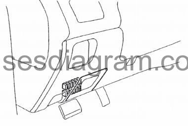
Fuse box in passenger compartment.
fuse box location.
fuse box diagram.
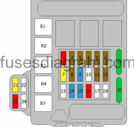
legend.
| Fuse | Amps | Circuits protected |
|---|---|---|
| 1 | 10A | Ignition coil Ignition coil relay |
| 2 | 7,5A | Combination meter Electric time and alarm control system (ETACS) SRS control unit Engine oil level sensor relay 4WD control unit Vehicle speed sensor |
| 3 | 7,5A | Rear combination light(s) Supplemental restraint system (SRS) |
| 4 | 7,5A | Not used |
| 5 | 7,5A | Air-conditioning compressor relay Air-conditioning control unit Blower relay Front control unit Intercooler water spray motor Demister relay Condenser fan relay |
| 6 | 7,5A | Electric mirrors |
| 7 | 20A | Front control unit Windscreen wiper motor |
| 8 | 7,5A | Engine control unit Fuel pump relay Fuel pump relay No. 2 |
| 9 | 15A | Cigarette lighter |
| 10 | Not used | |
| 11 | 7,5A | Electric mirror switch |
| 12 | 7,5A | ABS control unit G-force sensor 4WD control unit |
| 13 | Not used | |
| 14 | 15A | Electric time and alarm control system (ETACS) |
| 15 | 15A | Diagnostic system |
| 16 | 10A | Combination meter Rear fog light warning light Rear fog light relay |
| 17 | Not used | |
| 18 | Not used | |
| 19 | 30A | Blower motor Ignition coil |
| 20 | 30A | Demister |
| 21 | Not used | |
| 22 | Not used | |
| 23 | 10A | Intercooler water spray motor |
| 24 | Not used | |
| R1 | Fuel pump relay Additional relay, fuel pump | |
| R2 | Intercooler water spray motor relay | |
| R3 | Fuel pump relay No. 2 | |
| R4 | Not used | |
| R5 | Rear fog light relay |
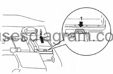
Fuse box in engine compartment.
fuse box location.
fuse box layout.
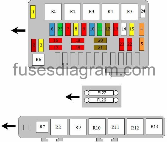
legend.
| Fuse | Amps | Circuits protected |
|---|---|---|
| 1 | 60A | Fuse box in passenger compartment, fuses 15, 16, 19, 20 |
| 2 | 50A | Fan control |
| 3 | 60A | ABS control unit |
| 4 | 40A | Ignition switch |
| 5 | 40A | Fuse box in passenger compartment, fuse 21 Window switches |
| 6 | 15A | Not used |
| 7 | 10A | Horn Horn relay |
| 8 | 20A | Engine control relay Engine control unit Ignition coil |
| 9 | 10A | Air-conditioning compressor |
| 10 | 15A | ABS control unit 4WD control unit Additional brake light(s) Rear combination light(s) |
| 11 | 30A | Condenser fan |
| 12 | 7,5A | Alternator |
| 13 | 10A | Electric time and alarm control system (ETACS) control unit |
| 14 | Not used | |
| 15 | 20A | Fuel pump relay Fuel pump with fuel gauge sensor |
| 16 | 10A | Headlight(s) |
| 17 | 10A | Headlight(s) Main beam indicator light |
| 18 | 10A | Headlights |
| 19 | 10A | Headlight(s) Headlight levelling switch |
| 20 | 7,5A | Air-conditioning control unit Ashtray illumination Cigarette lighter illumination Clock Combination meter Fog light Hazard warning light switch Intercooler water spray motor Rear combination light(s) Optional connector |
| 21 | 7,5A | Combination meter Number plate light(s) Rear combination light(s) Headlight(s) |
| 22 | 10A | Clock Combination meter Electric time and alarm control system (ETACS) control unit Front control unit Steering column control unit 4WD control unit |
| 23 | 10A | Clock Electric time and alarm control system (ETACS) control unit Optional connector |
| 24 | Not used | |
| 25 | 30A | Condenser fan |
| FL26 | 100A | Battery |
| FL27 | 60A | Pump control |
| R1 | Not used | |
| R2 | Horn relay | |
| R3 | Condenser fan relay (sub) | |
| R4 | Condenser fan relay | |
| R5 | Not used | |
| R6 | Fan control | |
| R7 | Not used | |
| R8 | Not used | |
| R9 | Not used | |
| R10 | Ignition coil relay | |
| R11 | Not used | |
| R12 | Engine control relay | |
| R13 | Air-conditioning compressor relay Or Horn |