For Dodge Avenger 2008, 2009, 2010, 2011, 2012, 2013, 2014 mode year.
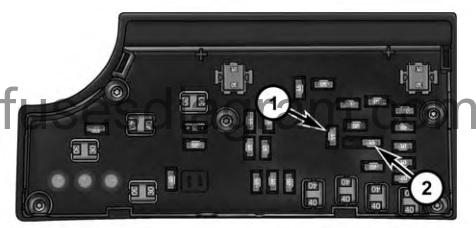
Cigar Lighter fuse 1- №16 Fuse 15 A Blue Cigar Lighter Instrument Panel 2 -№11 Fuse 15 A Blue Power Outlet Inside Arm Rest 3 – №13 Fuse 20 A Yellow Ignition/Cigar Lighter (If Equipped)
|
MENU
Totally integrated power module
- Assignment of the fuses (2008)
- Assignment of the fuses (2009-2011)
- Assignment of the fuses (2012-2014)
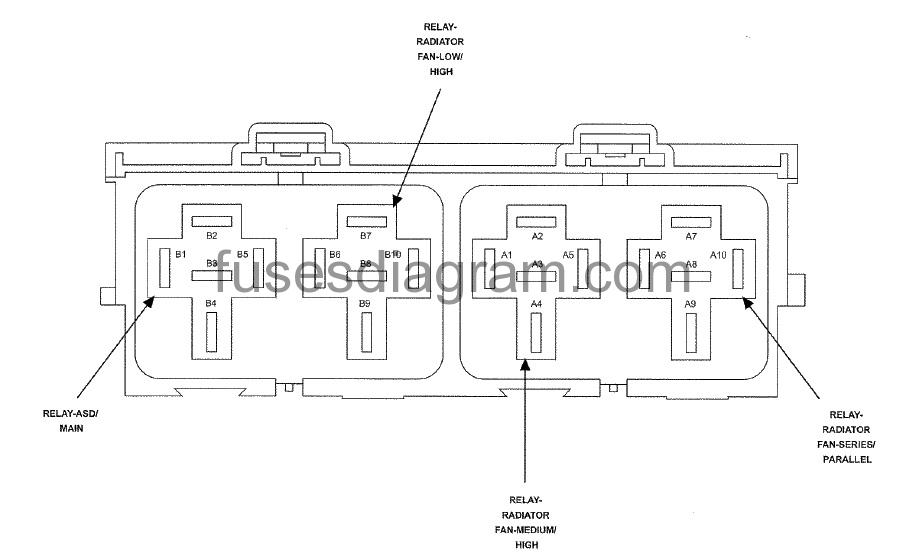
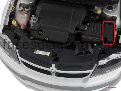
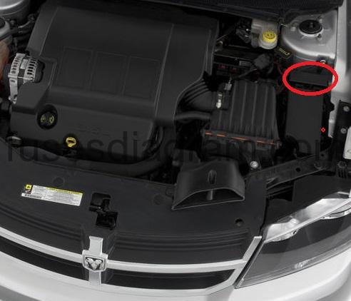
Totally integrated power module (tipm).
The TIPM is located in the engine compartment near the air cleaner assembly. This center contains cartridge fuses and mini fuses. A label that identifies each component may be printed on the inside of the cover. Refer to the following chart for FUSES/TIPM location.
fuse box diagram.
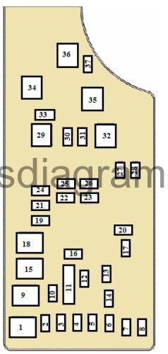
Assignment of the fuses (2008).
| FUSE NO. | AMPS | FUNCTION |
|---|---|---|
| 1 | 40A | Power Top Feed (Avneger) |
| 2 | 20A | AWD, ECU Feed (Avenger) |
| 3 | 10A | CHMSL Brake Switch Feed |
| 4 | 10A | Ignition Switch Feed |
| 5 | 20A | Trailer Tow |
| 6 | 10A | IOD Sw/ Pwr Mir/ Ocm Steering Cntrl Sdar/ Hfm |
| 7 | 30A | IOD Sense 1 |
| 8 | 30A | IOD Sense 2 |
| 9 | 40A | Power Seats/PZEV Air Pump |
| 10 | 20A | CCN Power Locks |
| 11 | 15A | Power Outlet |
| 12 | 20A | Ign Run/ Acc Inverter (Avenger) |
| 13 | 20A | Pwr Run/ Acc Outlet RR (Avenger) |
| 14 | 10A | IOD CCN/ Interior Lighting |
| 15 | 40A | RAD Fan Relay Batter Feed |
| 16 | 15A | IGN Run/ Acc Cigar Ltr/ Sunroof |
| 17 | 10A | IOD Feed Mod-WCM/Steering Control Module (SCM) |
| 18 | 40A | ASD Relay Contact PWR Feed |
| 19 | 20A | PWR Amp 1 & Amp 2 Feed |
| 20 | 15A | IOD Feed Radio |
| 21 | 10A | IOD Feed Intrus Mod/Siren (Avenger) |
| 22 | 10A | IGN RUN HVAC/ Compass Sensor/ Hot Cup Holder |
| 23 | 15A | ENG ASD Relay Feed 3 |
| 24 | 25A | PWR Sunroof Feed |
| 25 | 10A | Heated Mirror |
| 26 | 15A | ENG ASD Relay Feed 2 |
| 27 | 10A | IGN RUN Occupant Classification Module (OCM)/Only ORC Feed |
| 28 | 10A | IGN RUN ORC/OCM Feed |
| 29 | Hot Car (No Fuse Required) | |
| 30 | 20A | Heated Seats |
| 31 | 10A | Headlamp Washer Relay Control (Avenger) |
| 32 | 30A | ENG ASD Control Feed 1 |
| 33 | 10A | ABS MOD/J1962 Conn/PCM |
| 34 | 30A | ABS Valve Feed/Electronic Stability Program (ESP) Module |
| 35 | 40A | ABS Pump Feed/Electronic Stability Program (ESP) Module |
| 36 | 30A | Headlamp Washer Control (Avenger) |
| 36 | 30A | Passenger Door Module (PDM)/Driver Door Module (DDM) |
| 37 | 15A | 110 Inverter (Avneger) |
Assignment of the fuses (2009-2011).
| FUSE NO. | AMPS | FUNCTION |
|---|---|---|
| 1 | 40A | Power Top Module or not used |
| 2 | 20A | AWD Module or not used |
| 3 | 10A | Battery Feed – Center High Mounted Stop Light (CHMSL)/ Brake Switch |
| 4 | 10A | Battery Feed – Ignition Switch |
| 5 | 20A | Trailer Tow |
| 6 | 10A | Ignition Off Draw (IOD) – Power Mirror Switch/Climate Controls |
| 7 | 30A | Ignition Off Draw (IOD) Sense 1 |
| 8 | 30A | Ignition Off Draw (IOD) Sense 2 |
| 9 | 40A | Battery Feed – Power Seats/PZEV Air Pump |
| 10 | 20A | Battery Feed – Cabin Compartment Node (CCN) |
| 11 | 15A | Selectable Power Outlet |
| 12 | 20A | – |
| 13 | 20A | – |
| 14 | 10A | Ignition Off Draw (IOD) – Cabin Compartment Node (CCN)/ Interior Lighting |
| 15 | 40A | Battery Feed – Radiator Fan Relay |
| 16 | 15A | IGN Run/ Acc – Cigar Ltr/ Sunroof Mod |
| 17 | 10A | Ignition Off Draw (IOD) – Wireless Control Module (WCM)/Clock/Steering Control Module (SCM) |
| 18 | 40A | Battery Feed – Auto Shutdown (ASD) Relay |
| 19 | 20A | Ignition Off Draw (IOD) – Power Feed Amp 2 |
| 20 | 15A | Ignition Off Draw (IOD) – Radio |
| 21 | – | – |
| 22 | 10A | Ignition Run – Climate Controls/Hot Cup Holder |
| 23 | 15A | Auto Shutdown (ASD) Relay Feed 3 |
| 24 | 25A | Battery Feed – PWR Sunroof Feed |
| 25 | 10A | Ignition Run – Heated Mirror |
| 26 | 15A | Auto Shutdown (ASD) Relay Feed 2 |
| 27 | 10A | Ignition Run – Occupant Classification Module (OCM)/Occupant Restraint Controller (ORC) |
| 28 | 10A | Ignition Run – Occupant Classification Module (OCM)/Occupant Restraint Controller (ORC) |
| 29 | Hot Car (No Fuse Required) | |
| 30 | 20A | Ignition Run – Heated Seats |
| 31 | 10A | Headlight Washer Relay control (If equipped) |
| 32 | 30A | Auto Shutdown (ASD) Relay Feed 1 |
| 33 | 10A | Battery Feed – Switch Bank/Diagnostic Link Connector/Powertrain Control Module (PCM) |
| 34 | 30A | Battery Feed – Anti-Lock Brakes (ABS) Module/Electronic Stability Program (ESP) Module |
| 35 | 40A | Battery Feed – Anti-Lock Brakes (ABS) Module/Electronic Stability Program (ESP) Module |
| 36 | 30A | Battery Feed – Passenger Door Module (PDM)/Driver Door |
Assignment of the fuses (2012-2014).
| Cavity | Cartridge Fuse | Mini Fuse | Description |
|---|---|---|---|
| 1 | 40 Amp Green | – | Power Top Module – If Equipped |
| 2 | – | 20 Amp Yellow | Brake Vacuum Pump |
| 3 | – | 10 Amp Red | Center High Mounted Stop Light (CHMSL)/Brake Switch |
| 4 | – | 10 Amp Red | Ignition Switch |
| 5 | – | 20 Amp Yellow | Trailer Tow – If Equipped |
| 6 | – | 10 Amp Red | Power Mirror Switch/Climate Controls |
| 7 | – | 30 Amp Green | Ignition Off Draw (IOD) Sense 1 |
| 8 | – | 30 Amp Green | Ignition Off Draw (IOD) Sense 2 |
| 9 | 40 Amp Green | Battery Feed – Power Seats – If Equipped | |
| 10 | – | 20 Amp Yellow | Instrument Panel/Power Locks/Interior Lights |
| 11 | – | 15 Amp Lt Blue | Selectable Power Outlet (Inside Center Arm Rest) |
| 12 | – | 20 Amp Yellow | Spare |
| 13 | – | 20 Amp Yellow | Ignition/Cigar Lighter |
| 14 | – | 10 Amp Red | Instrument Panel |
| 15 | 40 Amp Green | – | Radiator Fan Relay |
| 16 | – | 15 Amp Lt. Blue | Sunroof – If Equipped |
| 17 | – | 10 Amp Red | Wireless Control Module (WCM)/Clock/Steering Control Module (SCM) |
| 18 | 40 Amp Green | – | Auto Shutdown (ASD) Relay |
| 19 | – | 20 Amp Yellow | Audio Amplifier – If Equipped |
| 20 | – | 15 Amp Lt. Blue | Radio |
| 21 | – | 10 Amp Red | Siren – If Equipped |
| 22 | – | 10 Amp Red | Ignition Run – Climate Controls/Hot Cupholder – If Equipped |
| 23 | – | 15 Amp Lt. Blue | Auto Shutdown (ASD) Relay 3 |
| 24 | – | 25 Amp Natural | Sunroof – If Equipped |
| 25 | – | 10 Amp Red | Ignition Run – Heated Mirrors – If Equipped |
| 26 | – | 15 Amp Lt. Blue | Auto Shutdown (ASD) Relay 2 |
| 27 | – | 10 Amp Red | Ignition Run – Occupant Classification Module (OCM)/Occupant Restraint Controller (ORC) |
| 28 | – | 10 Amp Red | Ignition Run – Occupant Classification Module (OCM)/Occupant Restraint Controller (ORC) |
| 29 | – | – | Hot Car (No Fuse Required) |
| 30 | – | 20 Amp Yellow | Ignition Run – Heated Seats – If Equipped |
| 31 | – | – | Spare |
| 32 | 30 Amp Pink | – | Auto Shutdown (ASD) Relay 1 |
| 33 | – | 10 Amp Red | Switch Bank/Diagnostic Link Connector/Powertrain Control Module (PCM) |
| 34 | 30 Amp Pink | – | Anti-Lock Brakes (ABS) Module – If Equipped/Electronic Stability Control (ESC) Module – If Equipped |
| 35 | 40 Amp Green | – | Anti-Lock Brakes (ABS) Module – If Equipped/Electronic Stability Control (ESC) Module – If Equipped |
| 36 | 30 Amp Pink | – | Passenger Door Module (PDM)/Driver Door Module (DDM) |
| 37 | – | 25 Amp Natural | Power Top Module – If Equipped |
fuse box diagram.