For Citroen Xsara Picasso 1999, 2000, 2001, 2002, 2003, 2004, 2005, 2006, 2007, 2008, 2009, 2010, 2011 model year.
Cigarette lighter fuse – fuse box in passenger compartment (type 1) – Fuse F23/20A Cigarette lighter fuse – fuse box in passenger compartment (type 2) – Fuse F22/20A |
MENU
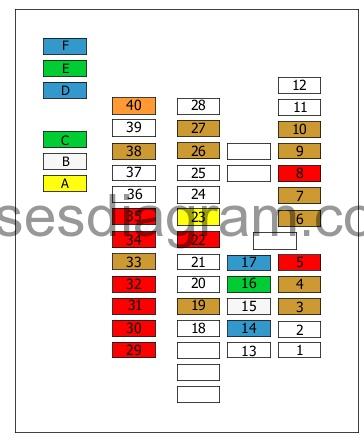
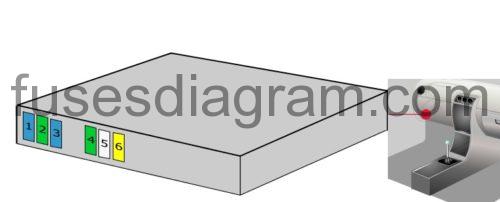
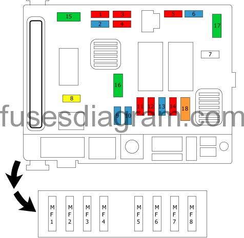
Fuse box in passenger compartment.
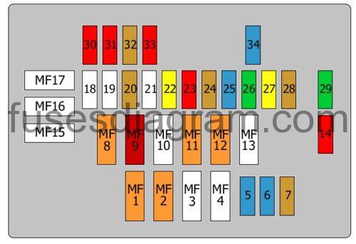
Fuse box No. 2 in passenger compartment.
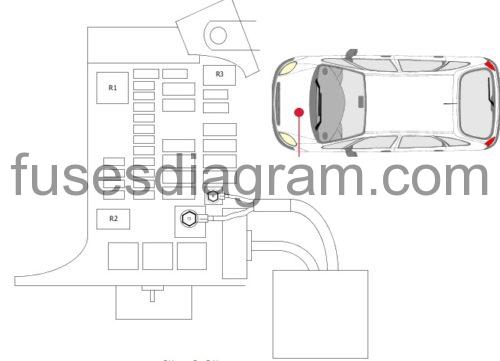
Fuse box in engine compartment.
- fuse box diagram (engine compartment type 1)
- fuse box diagram (engine compartment (type 2)
- fuse box diagram (engine compartment (type 3)
- fuse box diagram (engine compartment (type 4)
Relay box in engine compartment.
Fuse and relay box in engine compartment.
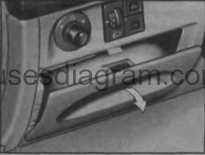
Fuse box in passenger compartment.
fuse box locaton.

Assignment of the fuses.
| F1 | Shunt resistor |
| F2 | – |
| F3 | (5A) Clutch pedal position (CPP) switch |
| F4 | (5A) Multifunction control module 1 |
| F5 | (10A) Brake pedal position (BPP) switch, instrument panel |
| F6 | (5A) Hazard warning lamps |
| F7 | (5A) Multifunction control module 1 |
| F8 | (5A) Instrument panel, interior lamps |
| F9 | (5A) Load area lamp |
| F10 | (10A) Navigation system |
| F11 | – |
| F12 | – |
| F13 | – |
| F14 | (15/30A) Accessories connector |
| F15 | – |
| F16 | (20A) Electric windows, sunroof |
| F17 | (5A) Audio system |
| F18 | – |
| F19 | (5A) Rear fog lamps |
| F20 | – |
| F21 | – |
| F22 | (10A) Glove box lamp, interior lamps, reading lamps, vanity mirror lamp – passenger |
| F23 | (20A) Accessories connector, cigarette lighter |
| F24 | (15A) Audio system |
| F25 | – |
| F26 | (5A) Interior rear view mirror |
| F27 | (10A) Multifunction control module 1 |
| F28 | – |
| F29 | (10A) LH headlamp – high beam |
| F30 | (10A) RH headlamp – high beam |
| F31 | (10A) LH headlamp – low beam |
| F32 | (10A) RH headlamp – low beam |
| F33 | (10A) Headlamp adjustment motor |
| F34 | (10A) LH front side lamp, LH tail lamp, licence plate lamps, headlamp switch, multifunction control module 1 |
| F35 | (10A) RH front side lamp, RH tail lamp |
| F36 | (15A) Auxiliary heater |
| F37 | |
| F38 | (5A) AC refrigerant pressure switch |
| F39 | |
| F40 | (40A) AC/heater blower motor |
legend.
| Fuses | Amps | Circuits Protected |
|---|---|---|
| F1 | 15 A | Diagnostic connector supply Trailer connector socket supply |
| F2 | — | |
| F3 | — | |
| F4 | 20 A | Switch module Radio Instrument panel Navigation Or Fuel additive control unit |
| F5 | 15 A | — |
| F6 | 10 A | Diagnostic connector Switch module |
| F7 | 15 A | Rain sensor Daylight running system Or Not used |
| F8 | — | |
| F9 | 30 A | Central locking, rear doors Sunroof motor |
| F10 | 40 A | Rear-view mirror Heated rear windscreen |
| F11 | 15 A | Rear wiper motor |
| F12 | 30 A | Front power windows Sunroof switch Rear power windows lock |
| F13 | — | |
| F14 | 10 A | Fuse box in engine compartment Airbag Seat belt pretensioners Or Fuel additive control unit |
| F15 | 15 A | Instrument panel Heater Radio Navigation Switch module Or Parking assistance control unit |
| F16 | 30 A | Central locking |
| F17 | — | |
| F18 | — | |
| F19 | — | |
| F20 | 10 A | Right tail light |
| F21 | 15 A | Left tail light Additional brake light(s) |
| F22 | 20А/30А | Rear-view mirror Front cigarette lighter Courtesy light(s) Glovebox illumination |
legend.
Fuse 1
Front airbags
Side airbags
Pretensioners
Fuse 2
Not used
Fuse 3
Not used
5.0 A
Fuse 4
Fuse box No. 2 in passenger compartment
5.0 A
Fuse 5
Stop switch (2.0 HDi control unit)
Instrument panel supply
10.0 A
Fuse 6
Hazard warning lights
5.0 A
Fuse 7
Fuse box No. 2 in passenger compartment
5.0 A
Fuse 8
Coolant temperature control unit
Interior light(s)
Instrument panel
10.0 A
Fuse 9
Luggage compartment light(s)
5.0 A
Fuse 10
Navigation system
5.0 A
Fuse 11
Not used
Fuse 12
Not used
Fuse 13
Not used
Fuse 14
Accessory socket
Trailer connector socket
15.0 A
Fuse 15
Rear power windows
25.0 A
Fuse 16
Front power windows
30.0 A
Fuse 17
Audio system
15.0 A
Fuse 18
Not used
Fuse 19
Fog light(s)
Fog light switch illumination
5.0 A
Fuse 20
Not used
Fuse 21
Not used
Fuse 22
Glovebox illumination
Interior light(s)
10.0 A
Fuse 23
Cigarette lighter
20.0 A
Fuse 24
Not used
Fuse 25
Not used
Fuse 26
Electric mirror(s)
5.0 A
Fuse 27
BSI (Intelligent power distribution module)
5.0 A
Fuse 28
Not used
Fuse 29
Left main beam
10.0 A
Fuse 30
Right main beam
10.0 A
Fuse 31
Right dipped beam
Headlight warning light
10.0 A
Fuse 32
Left dipped beam
Headlight warning light
10.0 A
Fuse 33
Headlight levelling
5.0 A
Fuse 34
Left sidelight
Left tail light
Number plate light(s)
10.0 A
Fuse 35
Right sidelight
Right tail light
10.0 A
Fuse 36
Not used
Fuse 37
Not used
Fuse 38
Not used
5.0 A
Fuse 39
Not used
Fuse 40
Air-conditioning blower
40.0 A
Fuse A
Central locking
20.0 A
Fuse B
Windscreen wiper(s)
25.0 A
Fuse C
Heated rear windscreen and mirrors
30.0 A
Fuse D
Air-conditioning compressor
15.0 A
Fuse E
Sliding roof
Front power windows
30.0 A
Fuse F
Multiplex system
15.0 A
Fuse box No. 2 in passenger compartment.
Fuse 1
Multiplex system
15.0 A
Fuse 2
Windows
Sunroof
30.0 A
Fuse 3
Air-conditioning compressor
15.0 A
Fuse 4
Heated mirror(s)
30.0 A
Fuse 5
Front wiper system
25.0 A
Fuse 6
Central locking
20.0 A
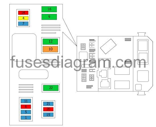
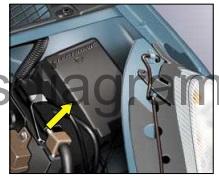
Fuse box in engine compartment.
To reach the fuses in the fusebox under the bonnet unclip the cover.
fuse box diagram (engine compartment type 1).
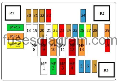
legend.
| R1 | Fog lamps relay |
| R2 | Auxiliary heater relay |
| R3 | Headlamp low beam relay |
| MF1 | (70A) Multifunction control module 1 |
| MF2 | (30A) Engine coolant blower motor (low speed) |
| MF3 | (30A) Engine coolant blower motor (high speed) |
| MF4 | (50A) Anti-lock brake system (ABS) |
| F5 | (15A) Horn |
| F6 | (15A) Headlamp low beam relay |
| F7 | (5A) Engine coolant blower motor relay |
| MF8 | (70A) Fuse box/relay plate, fascia 1 |
| MF9 | (50A) Multifunction control module 1 |
| MF10 | (40A) Headlamp switch |
| MF11 | – |
| MF12 | (50A) Ignition switch |
| MF13 | (40A) Ignition switch |
| F14 | (10A) Data link connector (DLC) |
| MF15 | (20A) Heated seats |
| MF16 | (40A) Fuse box/relay plate, fascia 1 |
| MF17 | (30A) Engine coolant heater |
| F18 | – |
| F19 | – |
| F20 | (5A) Engine coolant blower motor relay |
| F21 | – |
| F22 | (20A) Indicators |
| F23 | (10A) Anti-lock brake system (ABS) |
| F24 | (5A) Engine management |
| F25 | (15A) Engine management |
| F26 | (30A) Engine management |
| F27 | (20A) Relay module |
| F28 | (5A) Spare |
| F29 | (40A) Engine coolant heater |
| F30 | (5A) Front fog lamp, RH |
| F31 | (5A) Front fog lamp, LH |
| F32 | (5A) Vehicle speed sensor (VSS), reversing lamps |
| F33 | (10A) Engine coolant ‘low’ warning lamp switch, data link connector (DLC), fuel heater |
| F34 | (15A) Engine management |
Fuse box diagram (engine compartment (type 2).
legend.
| Fuses | Amps | Circuits Protected |
|---|---|---|
| 1 | 10 A | Reversing lights |
| 2 | 15 A | Fuel pump |
| 3 | 10 A | ABS control unit Or ESP control unit |
| 4 | 10 A | Automatic transmission control unit Engine control unit |
| 5 | 10 A | Diesel additive control unit |
| 6 | 15 A | Front fog lights |
| 7 | Headlight washer pump | |
| 8 | 20 A | Engine control unit relay |
| 9 | 15 A | Left dipped beam |
| 10 | 15 A | Right dipped beam |
| 11 | 10 A | Left main beam |
| 12 | 10 A | Right main beam |
| 13 | 15 A | Horn |
| 14 | 10 A | Front and rear washer pumps |
| 15 | 30 A | Engine control unit Oxygen sensor Injectors Ignition coils Canister purge solenoid |
| 16 | 30 A | Air pump |
| 17 | 30 A | Windscreen wiper |
| 18 | 40 A | Air-conditioning blower |
| MF1 | 50 А | Cooling fan |
| MF2 | 50 А | Anti-lock brakes |
| MF3 | 30 А | ESP |
| MF4 | 50 А | Fuse box No. 2 in passenger compartment |
| MF5 | 50 А | Fuse box No. 2 in passenger compartment |
| MF6 | — | Heated seat(s) |
| MF7 | 50 А | Ignition coils |
| MF8 | 70 А | Air conditioning |
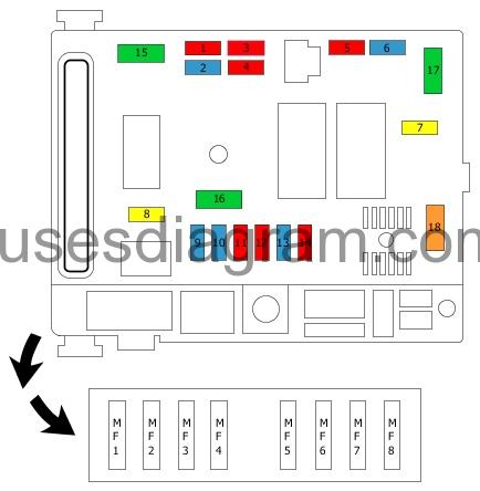
Fuse box diagram (engine compartment (type 3).
legend.
Fuse 1
Heater
Speed sensor
Automatic gearbox
Reversing light switch
Coolant level
Cooling fan relay, stage 2
Mass airflow meter
Automatic transmission selector handle lock
Start inhibitor relay
10.0 A
Fuse 2
Fuel gauge
Fuel pump
15.0 A
Fuse 3
Anti-lock brakes
ESP control unit
Or
Lateral acceleration sensor
10.0 A
Fuse 4
Injection control unit
Automatic transmission control unit
10.0 A
Fuse 5
Automatic transmission control unit
10.0 A
Fuse 6
Front fog light(s)
15.0 A
Fuse 7
Not used
Fuse 8
Injection control unit
Fuel pressure regulator, diesel
Cooling fan relay, stage 1
Mass airflow meter with air temperature sensor
Water in fuel sensor
Engine control unit
Cooling fan, low speed
Two-speed cooling fan
20.0 A
Fuse 9
Left headlight levelling
15.0 A
Fuse 10
Right headlight
15.0 A
Fuse 11
Left headlight
10.0 A
Fuse 12
Right headlight
10.0 A
Fuse 13
Horn
15.0 A
Fuse 14
Front and rear washer pumps
10.0 A
Fuse 15
Ignition coil
Oxygen sensor in front of the catalytic converter
Oxygen sensor behind the catalytic converter
Injectors (cylinders 1 – 4)
Canister purge solenoid(s)
Injection pump, diesel
Carburettor heating
EGR system
Turbo regulation solenoid
Oil heater
Or
30.0 A
Fuse 16
Turbocharger
30.0 A
Fuse 17
Windscreen wiper motor
30.0 A
Fuse 18
Blower
Air-conditioning thermostat
Fuse box No. 2 in engine compartment
40.0 A
Fuse MF1
(80A also used)
Cooling fan relay, stage 1
Cooling fan relay, stage 2
20.0 A
Fuse MF2
(80A also used)
Anti-lock brakes
ESP control unit
20.0 A
Fuse MF3
(80A also used)
Anti-lock brakes
20.0 A
Fuse MF4
(80A also used)
Fuse box No. 2 in passenger compartment
20.0 A
Fuse MF5
(80A also used)
Fuse box No. 2 in passenger compartment
20.0 A
Fuse MF6
(80A also used)
Fuse box No. 1 in passenger compartment
Or
Not used
Fuse MF7
(80A also used)
Ignition switch
20.0 A
Fuse MF8
(80A also used)
Additional heater
20.0 A
Fuse box diagram (engine compartment (type 4).
Fuse 5
Warning system
15.0 A
Fuse 6
Remote control relay
15.0 A
Fuse 7
Cooling fan
5.0 A
Fuse 14
Diagnostic connector
10.0 A
Fuse 18
Not used
Fuse 19
Not used
Fuse 20
Cooling fan
5.0 A
Fuse 21
Not used
Fuse 22
Fuse box No. 2 in passenger compartment
Direction indicators
20.0 A
Fuse 23
ABS control unit
10.0 A
Fuse 24
Injection control unit
5.0 A
Fuse 25
Fuel pump
15.0 A
Fuse 26
No information is available
30.0 A
Fuse 27
No information is available
20.0 A
Fuse 28
Cooling fan
5.0 A
Fuse 29
No information is available
30.0 A
Fuse 30
Front right fog light
10.0 A
Fuse 31
Front left fog light
10.0 A
Fuse 32
Speed sensor
Reversing light(s)
5.0 A
Fuse 33
Coolant temperature control unit
Diagnostic connector
10.0 A
Fuse 34
Catalytic converter
15.0 A
Fuse MF1
No information is available
40.0 A
Fuse MF2
No information is available
40.0 A
Fuse MF3
No information is available
60.0 A
Fuse MF4
No information is available
60.0 A
Fuse MF8
No information is available
40.0 A
Fuse MF9
No information is available
50.0 A
Fuse MF10
No information is available
70.0 A
Fuse MF11
No information is available
40.0 A
Fuse MF12
No information is available
40.0 A
Fuse MF13
No information is available
70.0 A
Fuse MF15
No information is available
80.0 A
Fuse MF16
No information is available
80.0 A
Fuse MF17
No information is available
80.0 A
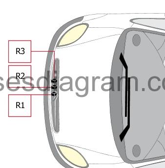
Relay box in engine compartment.
Relay R1
Air pump
Or
Additional heater
or not used
Relay R2
Front fog lights
Relay R3
Dipped beam
Fuse and relay box in engine compartment.
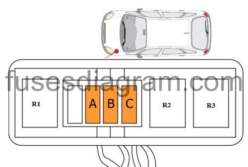
Fuse A
Air-conditioning heater control
40.0 A
Fuse B
Air-conditioning heater control
40.0 A
Fuse C
Air-conditioning heater control
40.0 A
Relay R1
Heater relay
Relay R2
Heater relay
Relay R3
Heater relay
Relay R1
Cooling fan, high-speed relay
Relay R2
Cooling fan, medium-speed relay
Relay R3
Cooling fan, low-speed relay