For Citroen Jumper 3 /Relay 3 2006, 2007, 2008, 2009, 2010, 2011, 2012, 2013, 2014, 2015, 2016, 2017, 2018 model year.
Cigarette lighter fuse – fuse box in passenger compartment – Fuse F44/20A or Cigarette lighter fuse – fuse box in engine compartment – Fuse F15/10A |
MENU
Fuse and relay box in passenger compartment.
- fuse box diagram (type 1)
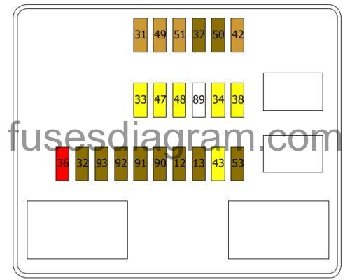
- fuse box diagram (type 2)
- additional fuse and relay box in passenger compartment, with transformer socket
- fuse box in passenger’s door pillar
Fuse box in engine compartment.
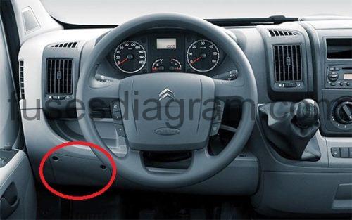
Fuse and relay box in passenger compartment.
fuse box location.
in the dashboard on the left-hand side.
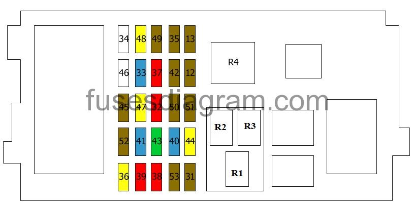
Assignment of the fuses.
| Fuses | Amps | Circuits Protected |
|---|---|---|
| 12 | 7.5A | Right dipped beam Rear right sidelight |
| 13 | 7.5A | Left dipped beam Headlight levelling |
| 31 | 7.5A | Relay box Feed to built-in systems interface Parking assistance |
| 32 | 10A | Interior light |
| 33 | 15A | Rear 12V socket |
| 34 | Not used | |
| 35 | 7.5A | Cruise control Reversing light Water in fuel sensor Mass airflow meter |
| 36 | 20A | Central locking control unit |
| 37 | 10A | Brake light switch Control panel Additional brake light |
| 38 | 10A | Relays |
| 39 | 10A | Radio Diagnostic socket Telephone control unit Alarm siren Additional heater control Heater panel Air-conditioning switch Tachograph |
| 40 | 15A | Heated rear windscreen, left side Heated mirrors |
| 41 | 15A | Heated rear windscreen, right side Heated mirrors |
| 42 | 7.5A | ABS control unit ESP sensor ABS G-sensor Brake light switch |
| 43 | 30A | Windscreen wiper motor |
| 44 | 20A | Front cigarette lighter Rear 12V socket |
| 45 | 7.5A | Power windows Rear-view mirror Passenger’s power window switch |
| 46 | Not used | |
| 47 | 20A | Driver’s power window |
| 48 | 20A | Power window, passenger’s side |
| 49 | 7.5A | Parking assistance control unit Rain and light sensor Multifunction switch Telephone control unit Driver’s power window Heated seats Parking assistance |
| 50 | 7.5A | Airbags and pretensioners unit |
| 51 | 7.5A | Power steering control unit Feed to built-in systems interface Tachograph |
| 52 | 7.5A | Relay box Fuse box in passenger compartment |
| 53 | 7.5 | Control panel Rear fog light |
| R1 | Dipped beam relay | |
| R2 | Heated rear windscreen relay | |
| R3 | Service indicator | |
| R4 | Service indicator |
legend.
| Fuses | Amps | Circuits Protected |
|---|---|---|
| 12 | 7.5A | Headlights, dipped beam |
| 13 | 7.5A | Headlights, dipped beam |
| 31 | 5A | Fuse and relay box in engine compartment Fuse box in passenger compartment |
or
(3A) Engine compartment control unit relay – Dashboard control unit relay (ignition switch +)
32
7.5A
Not used
or
Cabin lighting (battery +)
33
20A
Not used
or
Battery check sensor on Stop & Start version (battery +)
34
20A
Not used
or
(7.5A) Minibus interior lighting – Hazard warning lamps
36
10A
Audio system
Air-conditioning control
Alarm
Tachograph
Battery cut-out
WEBASTO timer
37
7.5A
Brake light(s) switch
Additional brake light
Instrument panel
38
20A
Door lock
42
5A
ABS
ASR
ESP
Brake light switch
43
20A
Windscreen wiper
47
20A
Driver’s power window
48
20A
Passenger’s power window
49
5A
Parking assistance control unit
Audio system
Steering wheel controls
Control panel
Battery cut-out
50
7.5A
Airbag
51
5A
Air-conditioning control unit
Power steering control unit
Reversing light(s)
Water in fuel sensor
Mass airflow meter
Tachograph
53
7.5
AInstrument panel
90
7.5
Left-hand main beam
91
7.5A
Right headlight, main beam
92
7.5A
Left fog light
93
7.5A
Right fog light
Additional fuse and relay box in passenger compartment, with transformer socket.
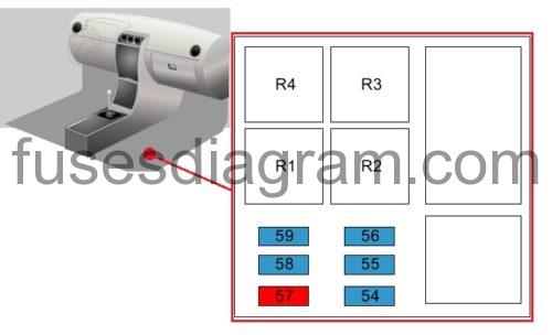
legend.
| Fuses | Amps | Circuits Protected |
|---|---|---|
| 54 | 15A | Air conditioning |
| 55 | 15A | Heated seats |
| 56 | 15A | Rear 12V socket |
| 57 | 10A | Additional heater |
| 58 | 15A | Rear demister |
| 59 | 15A | Rear demister |
| R1 | Interior light(s) relay | |
| R2 | Heated seats | |
| R3 | Additional heater relay Or Air conditioning | |
| R4 | Heated seats |
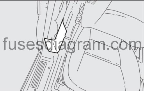
Fuse box in passenger’s door pillar.
The fusebox is located in the passenger’s door pillar (right-hand side).
fuse box diagram.
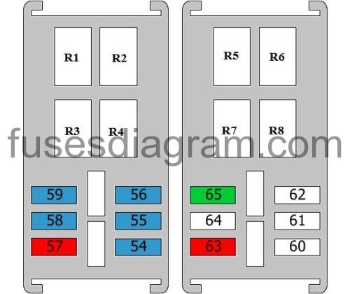
legend
| Fuses | Amps | Circuits Protected |
|---|---|---|
| 54 | 15A | Ventilation control |
| 55 | 15A | Heated seats |
| 56 | 15A | Rear 12V socket |
| 57 | 10A | Heating Additional heater |
| 58 | 15A | Heated rear windscreen, left side or (10A) Direction indicators or (10A) Lateral sidelamps |
| 59 | 15A | Heated rear windscreen, right side or (7.5A) Pneumatic suspension |
| 60 | Not used | |
| 61 | Not used | |
| 62 | Not used | |
| 63 | 10A | Additional heater Or Air conditioning |
| 64 | Not used | |
| 65 | 30A | Additional heater Or Air conditioning |
| R1 | Heated windscreen | |
| R2 | Not used | |
| R3 | Interior light | |
| R4 | Heated seats | |
| R5 | Additional heater Or Air conditioning | |
| R6 | Not used | |
| R7 | Additional heater Or Air conditioning | |
| R8 | Additional heater Or Air conditioning |
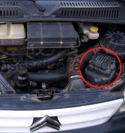
Fuse box in engine compartment.
fuse box location.
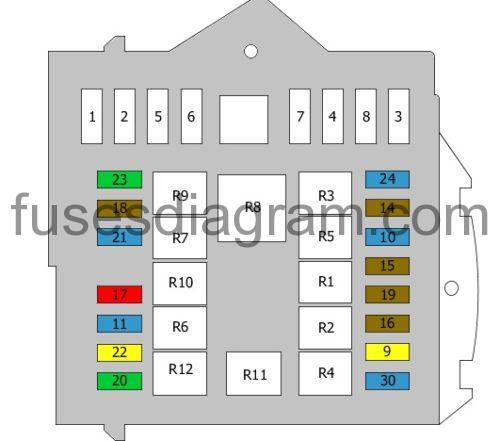
legend.
| Fuses | Amps | Circuits Protected |
|---|---|---|
| 1 | 40A | ABS hydraulic unit and pump ESP pump |
| 2 | 50A | Pre-post heating |
| 3 | 30A | Ignition switch |
| 4 | 20A | Additional heater |
| 5 | 20A | Additional relay, heater control |
| 6 | 40A | Cooling fan, high speed (60A also used) |
| 7 | 40A | Cooling fan, low speed (50A also used) |
| 8 | 40A | Air conditioning system |
| 9 | 20A | Windscreen washer pump |
| 10 | 15A | Horn |
| 11 | 15A | Pre-post heating Heater relay |
| 14 | 7.5A | Right main beam |
| 15 | 7.5A | Left main beam |
| 16 | 7.5A | Engine control unit |
| 17 | 10A | Engine control unit |
| 18 | 7.5A | Engine control unit |
| 19 | 7.5A | Air-conditioning compressor |
| 20 | 30A | Headlight washer |
| 21 | 15A | Fuel supply pump |
| 22 | 20A | Engine control unit |
| 23 | 30A | ABS (hydraulic unit) ESP hydraulic unit |
| 24 | 15A | Rear-view mirror or not used |
| 30 | 15A | Rear fog lights |
| R1 | Horn relay | |
| R2 | Front fog light relay | |
| R3 | Main beam relay | |
| R4 | Windscreen washer pump | |
| R5 | Air-conditioning relay | |
| R6 | Not used | |
| R7 | Fuel pump relay | |
| R8 | Cooling fan, low speed | |
| R9 | Cooling fan, high speed | |
| R10 | Engine control unit relay Or Fuel pump | |
| R11 | Air-conditioning compressor relay | |
| R12 | Headlight washer pump relay |
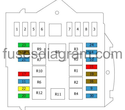
legend.
| Fuses | Amps | Circuits Protected |
|---|---|---|
| 1 | 40A | ABS hydraulic unit and pump |
| 2 | 50A | Pre-post heating |
| 3 | 30A | Ignition switch |
| 4 | 30A | Headlight washer or Fuel heater |
| 5 | 20A | Fuel vaporiser system pump or (50) Cabin ventilation with additional programmable heating (battery +) |
| 6 | 40A | Cooling fan, high speed (60A also used) |
| 7 | 40A | Cooling fan, low speed (50A also used) |
| 8 | 40A | Air conditioning system or Cabin fan assembly (ignition switch +) |
| 9 | 15A | Not used or Rear 12 V socket (battery +) |
| 10 | 15A | Horn |
| 11 | 15A | Electronic injection |
| 14 | 15A | Front 12V socket |
| 15 | 10A | Cigarette lighter |
| 16 | 7.5A | Electronic injection |
| 17 | 10A | Electronic injection |
| 18 | 7.5A | Electronic injection |
| 19 | 7.5A | Air-conditioning compressor |
| 20 | 30A | Windscreen wiper |
| 21 | 15A | Fuel pump |
| 22 | 20A | Electronic injection |
| 23 | 30A | ABS (hydraulic unit) |
| 24 | 15A | Rear-view mirror |
| 30 | 15A | Heated mirrors |
| R1 | Horn relay | |
| R2 | Heated mirror relay | |
| R3 | Front 12V socket Cigarette lighter | |
| R4 | Rear 12V socket | |
| R5 | Air-conditioning relay | |
| R6 | Not used | |
| R7 | Fuel pump relay | |
| R8 | Cooling fan, low speed | |
| R9 | Cooling fan, high speed | |
| R10 | Electronic injection | |
| R11 | Air-conditioning compressor relay | |
| R12 | Windscreen wiper relay |
Additional fuse box in engine compartment.
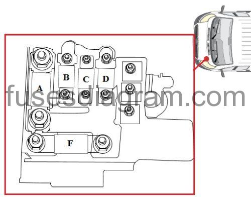
Fuse A
Fuse and relay box in engine compartment
150.0 A
Fuse B
Fuse and relay box in passenger compartment
80.0 A
Fuse C
Fuse and relay box in passenger compartment
70.0 A
Fuse D
Ignition transformer
50.0 A
Fuse F
Additional fuse box in engine compartment