
For the Ford Focus MK2 2004, 2005, 2006, 2007, 2008, 2009, 2010, 2011 model year (Europe, USA).
Fuse box in passenger compartment.
fuse box location.
type 1 (USA).
The fuse panel is located below and to the left of the steering wheel by the brake pedal. Remove the CD stowage box to access the fuses.
fuse box diagram.
type 1 (USA).
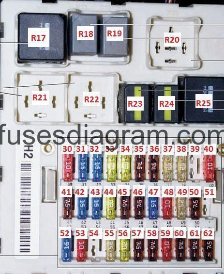
legend (early production).
Fuse | Amps | Circuits protected |
|---|---|---|
F30 | 10 | Main light switch |
F31 | 20 | Radio |
F32 | 15 | Generic Electronic Module (GEM) |
F33 | 20 | Power seats, Horn |
F34 | 20 | Roof opening panel unit, Luggage compartment lid release relay |
F35 | 7.5 | Battery saver |
F36 | 7.5 | Instrument cluster, Heater control module, Battery saver relay |
F37 | – | not used |
F38 | – | not used |
F39 | – | not used |
F40 | 10 | Reversing lamps (auto) |
F41 | 7.5 | Radio, Instrument cluster |
F42 | 10 | Stop lamps, Brake pedal position (BPP) switch |
F43 | 15 | Wiper/washer, Rear, Power sliding roof |
F44 | – | not used |
F45 | 7.5 | Heater control module |
F46 | – | not used |
F47 | 20 | Cigar lighter, front |
F48 | 10 | Data Link Connector (DLC) |
F49 | 25 | Rear window defrost grid |
F50 | 7.5 | Heated mirrors |
F51 | 7.5 | Seat weight sensor module, Hasard flasher switch |
F52 | 15 | Heated seats |
F53 | 10 | speed control, Reversing lamps (manual) |
F54 | 25 | Master window adjust switch, rear windows |
F55 | 25 | Power Windows, front windows |
F3.56 | 20 | Wiper and Washer |
F57 | – | not used |
F58 | – | not used |
F59 | 7.5 | Headlamps, Multifunction switch |
F60 | 7.5 | Restraints control module |
F61 | 7.5 | Passive anti-theft transceiver module, Instrument cluster |
F62 | 7.5 | Audio Unit |
F63 | 20 | Generic Electronic Module (GEM) |
Fuse | Amps | Circuits protected |
F30 | 10 | Main light switch |
F31 | 20 | Radio |
F32 | 15 | Generic Electronic Module (GEM) |
F33 | 20 | Roof opening panel |
F34 | 20 | Horn |
F35 | 7.5 | Instrument cluster, Heater control module, Battery saver relay |
F36 | 7.5 | Battery saver, Interior lamps, power mirror |
F37 | – | not used |
F38 | – | not used |
F39 | 2 | Power hold relay, Igntion relay |
F40 | 25 | Rear window defrost grid |
F41 | – | not used |
F42 | 10 | Stoplamps, Brake Pedal Position (BPP) switch |
F43 | 15 | Wiper/washer, Rear, Roof opening panel |
F44 | 15 | daytime running lamps |
F45 | 7.5 | Heater control module |
F46 | – | not used |
F47 | 20 | Cigar lighter, front |
F48 | 10 | Data Link Connector (DLC) |
F49 | 7.5 | Heated mirror |
F50 | 10 | Reversing lamps |
F51 | 7.5 | Seat weight sensor module, Hazard flasher switch |
F52 | 15 | Heated seats |
F53 | 10 | speed control, Park/neutral position (PNP) switch |
F54 | 25 | Master window adjust switch, rear windows |
F55 | 25 | Power Windows, front windows |
F56 | 20 | Wiper and Washer |
F57 | 7.5 | Radio, Instrument cluster |
F58 | – | not used |
F59 | 7.5 | Headlamps, Multifunction switch |
F60 | 7.5 | Restraints control module |
F61 | 7.5 | Passive anti-theft transceiver module, Instrument cluster |
F62 | 7.5 | Audio Unit |
F63 | 20 | Generic Electronic Module (GEM) |
| Relay | Description | |
| R17 | Starter | |
| R18 | Rear intermittent wiper (may be incorporated with relay 19) | |
| R19 | Front intermittent wiper (may be incorporated with relay 18) | |
| R20 | Not used | |
| R21 | Not used | |
| R22 | Not used | |
| R23 | Horn | |
| R24 | Battery saver | |
| R25 | Rear defrost | |
fuse box location.
type 2 (USA).
The fuse panel is located below and to the left of the steering wheel by the brake pedal. Remove the fuse panel cover to gain access to the fuses.
fuse box diagram.
type 2 (USA).

legend.
R1 – Accessory delay relay.
Fuse/Relay Location | Fuse Amp Rating | Smart Junction Box Description |
1 | 30A | Not Used (SPARE) |
2 | 15A | Brake Pedal Position Switch, High Mounted Stop lamp |
3 | 15A | Satellite Digital Audio Receiver System (SDARS) Module |
4 | 30A | Not Used (SPARE) |
5 | 10A | Floor Shifter |
6 | 20A | Park/Stop/Turn lamp, LR and RR, Park/Turn lamp, LF and RF |
7 | 10A | Low Beam, Headlamp Left |
8 | 10A | Low Beam, Headlamp Right |
9 | 15A | Interior/Map Lamps Assembly, Front |
10 | 15A | Panel Illumination |
11 | 10A | Not Used (SPARE) |
12 | 7.5A | Exterior Rear View Mirror Switch |
13 | 5A | Accessory Protocol Interface Module (APIM) |
14 | 10A | Not Used (SPARE) |
15 | 10A | HVAC Module |
16 | 15A | Not Used (SPARE) |
17 | 20A | All Lock Relay, All Unlock Relay, Driver Unlock Relay, Luggage Compartment Lid Release Relay |
18 | 20A | Heated Seat Relays, Driver and Passenger |
19 | 25A | Roof Opening Panel Module |
20 | 15A | Data Link Connector (DLC) |
21 | 15A | Fog Lamp Relay |
22 | 15A | Park Lamp Relay |
23 | 15A | High Beam Relay, Headlamps |
24 | 20A | Horn Relay |
25 | 10A | Battery Saver Relay |
26 | 10A | Instrument Cluster |
27 | 20A | Ignition Switch |
28 | 5A | Audio Control Module (ACM) |
29 | 5A | Instrument Cluster (IC) |
30 | 5A | Not Used (SPARE) |
31 | 10A | Anti-Lock Brake System (ABS) Module |
32 | 10A | Restraints Control Module (RCM) |
33 | 10A | Not Used (SPARE) |
34 | 5A | Not Used (SPARE) |
35 | 10A | Not Used (SPARE) |
36 | 5A | Passive Anti-Theft Transceiver Module |
37 | 10A | HVAC Module |
38 | 20A | Subwoofer Amplifier |
39 | 20A | Audio Control Module (ACM), Front Control Interface Module (FCIM), Front Display Interface Module (FDIM) |
40 | 20A | Not Used (SPARE) |
41 | 15A | Ambient Lighting, Roof Opening Panel Control Switch, Electrochromatic Inside Mirror Unit, Driver and Passenger Door Lock Switch Illumination |
42 | 10A | Not Used (SPARE) |
43 | 10A | Heated Seat Relays |
44 | 10A | Not Used (SPARE) |
45 | 5A | Wiper Power Relay |
46 | 7.5A | Occupant Classification Sensor (OCS) Module, PAD Indicator/Traction Control/Ambient Lighting Switch |
47 | 30A C.B. | Roof Opening Panel Module, Master Window Control Switch, Window Control Switch, Passenger Side (Coupe) |
fuse box location.
type 3 (Europe).
1 – Remove the screws in the instrument panel trim underneath the glove compartment and lower the trim panel.
2 – Loosen the screws.
3 – Lower the fuse box and pull it towards you.
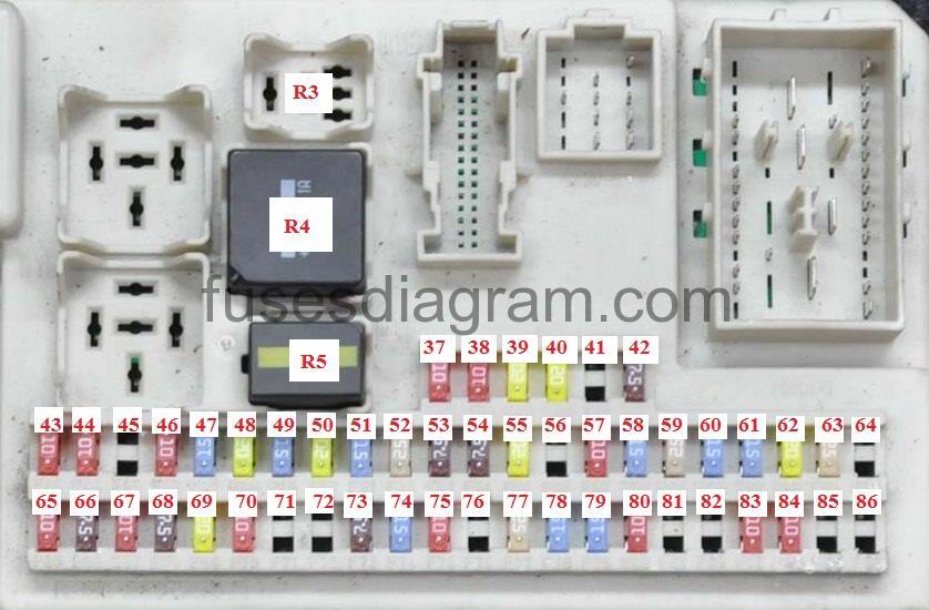
fuse box diagram.
type 3 (Europe).
1 | – |
2 | – |
R3 | Daytime running lamps relay |
R4 | Heated rear window relay |
R5 | Fuel pump (FP) relay |
F37 | (10A) LH headlamp |
F38 | (10A) RH headlamp |
F39 | (20A) Cigarette lighter |
F40 | (20A) Sunroof |
F41 | (20A) Door function control module, passenger |
F42 | (7,5A) Electric door mirrors |
F43 | (10A) Fuel additive control module, heater function control module, keyless entry control module, steering column adjustment module |
F44 | (10A) Data link connector (DLC) |
F45 | (10A) Ignition switch, light switch |
F46 | (10A) Instrument panel |
F47 | (15A) Windscreen washer jet heaters |
F48 | (20A) Daytime running lamps |
F49 | (15A) Light switch |
F50 | (20A) Windscreen wipers – low speed |
F51 | (15A) Fuel pump (FP) relay |
F52 | (25A) Heated rear window |
F53 | (7,5A) LH tail lamp, LH headlamp |
F54 | (7,5A) RH tail lamp, RH headlamp |
F55 | (20A) Door function control module, driver |
F56 | (20A) Keyless entry control module |
F57 | (10A) Door mirror retract control module, alarm system horn |
F58 | (15A) Alarm system, navigation system, touch screen display |
F59 | (20A) Trailer control module |
F60 | (15A) RH headlamp |
F61 | (15A) LH headlamp |
F62 | (20A) Electric seats |
F63 | (25A) Electric door mirrors, electric windows |
F64 | – |
F65 | (10A) Supplementary restraint system (SRS) |
F66 | (7,5A) Gas discharge headlamp control module, light switch |
F67 | (10A) Alarm system, instrument panel |
F68 | (7,5A) Alarm system, audio system, instrument panel, navigation system |
F69 | (20A) Light switch |
F70 | (10A) Fuel additive control module, hazard warning lamps, heated rear window, heated seats, heated windscreen, heater function control module, parking aid control module, sunroof, windscreen wiper rain sensor |
F71 | (10A) Light switch |
F72 | (25A) Multifunction control module |
F73 | (7,5A) Licence plate lamps |
F74 | (15A) Stop lamps |
F75 | (10A) Engine management, accelerator pedal position (APP) sensor, transmission control module (TCM) |
F76 | (7,5A) Parking brake control module |
F77 | (25A) Central locking |
F78 | (15A) Rear screen wash/wipe system |
F79 | (15A) Auxiliary power socket |
F80 | (10A) Battery saver relay |
F81 | (20A) Door function control module, right rear |
F82 | (20A) Door function control module, left rear |
F83 | (10A) Audio system – rear |
F84 | (10A) Electric windows, reversing lamps |
F85 | – |
F86 | (20A) Heated seats |
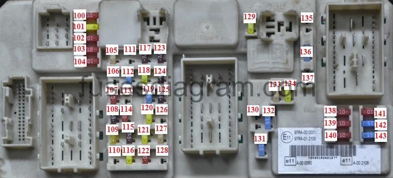
fuse box diagram.
type 4 (Europe – update).
Fuse | Ampere rating | Circuits protected |
|---|---|---|
100 | 10 | Electronic modules ignition supply |
101 | 20 | Electric sunroof control module, driver’s electric seat, roof control module (convertible only) |
102 | 10 | Heater control, steering column, diesel particulate filter, remote control receiver |
103 | 10 | Lighting control battery supply |
104 | 10 | Battery saver, interior lamps |
105 | 25 | Heated rear window |
106 | 20 | Keyless system |
107 | 10 | Instrument cluster battery supply, on-board diagnostics |
108 | 7.5 | Accessory to cluster (audio and navigation unit) |
109 | 20 | Cigar lighter, rear auxiliary power socket |
110 | 10 | Daytime running lamps ignition supply to lighting control switch |
111 | 15 | Fuel pump (petrol engine only) |
112 | 15 | Audio modules battery supply |
113 | 10 | Daytime running lamps (parking lamps) |
114 | 10 | Instrument cluster ignition supply, engine immobiliser |
115 | 7.5 | Lighting control ignition supply |
116 | 20 | Fog lamps |
117 | 7.5 | Number plate lamps |
118 | 20 | Door module, left-hand rear |
119 | 15 | Luggage compartment auxiliary power socket |
119 | 25 | Luggage compartment auxiliary power socket (vehicles with trailer tow module) |
120 | 20 | Door module, right-hand rear |
121 | 20 | Heated front seats |
122 | 10 | Airbag module |
123 | 7.5 | Heated exterior mirrors |
124 | 7.5 | Parking lamps, side lamps, tail lamps (left-hand side) |
125 | 7.5 | Parking lamps, side lamps, tail lamps (right-hand side) |
126 | 20 | Keyless system |
127 | 25 | Electric windows |
128 | – | Not used |
129 | 20 | Windscreen wipers |
130 | – | Not used |
131 | 15 | Rear window wiper |
132 | 15 | Brake lamps |
133 | 25 | Central locking relays, passenger door module |
134 | 20 | Central locking, driver door module |
135 | 20 | Daytime running lamps |
136 | 15 | Washer pump, heated washer jets |
137 | 10 | Battery backup sounder |
138 | 10 | Powertrain control module, accelerator pedal, automatic transmission |
139 | 10 | Main beam right-hand side |
140 | 10 | Main beam left-hand side |
141 | 10 | Reversing lamp, electric mirrors |
142 | 15 | Dipped beam, right-hand side |
143 | 15 | Dipped beam, left-hand side |
Fuse box in engine compartment.
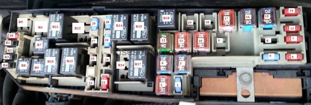
fuse box diagram.
type 1 (USA).
Fuse | Amps | Circuits protected |
F1 | 40 | Central Junction Box (CJB), Speed control servo, AB S control module |
F2 | – | not used |
F3 | – | not used |
F4 | 30 | Air pump motor |
F5 | 30 | ABS control module |
F6 | 50 | High speed fan control relay, Engine cooling fan relay |
F7 | 40 | Central Junction Box (CJB) |
F8 | 30 | Starting System, Ignition switch |
F9 | 20 | Electronic Engine Controls, Heated oxygen sensors (HO2S), Engine Ignition, Fuel injectors, Digital Transmission Range (DTR) sensor, Gearshift lever unit to transmission overdrive cancel switch, Engine Cooling, Fuel pump relay |
F10 | 1 | Generator |
F11 | 30 | Subwoofer amplifier |
F12 | 15 | Inertia Fuel Shutoff (IFS) switch, Fuel pump driver module |
F13 | 20 | ABS control module |
F14 | – | not used |
F15 | not used | |
F16 | 10 | Low beam, Left |
F17 | 10 | Low beam, Right |
F18 | 15 | Heated oxygen sensors (HO2S) |
F19 | 40 | Heater blower motor |
F20 | 10 | Power train Control Module (PCM) |
F21 | 10 | A/C clutch relay |
F22 | 20 | Low beam, Low beam relay |
F23 | 15 | High beam relay and fog lamps |
F24 | not used | |
F25 | – | not used |
F26 | not used | |
F27 | not used | |
F28 | 1 | ABS control module |
F29 | 10 | Speed control servo, AB S control module (2) |
Relay.
| Relay | Description |
| R1 | Ignition |
| R2 | Not used |
| R3 | Not used |
| R4 | Not used |
| R5 | High beams |
| R6 | Low beams |
| R7 | Fuel pump |
| R8 | Engine management |
| R9 | Not used |
| R10 | Not used |
| R11 | Air conditioning |
| R12 | Daytime running lights |
| R13 | Fog lamps |
| R14 | Stop iamp inhibit relay (AdvanceTrac® ortlv) |
| R15 | Engine cooling fan level 2 (A/C) |
| R16 | Engine cooling fan level 1 |
Fuse box diagram (USA).
type 2.
Fuse/Relay Location | Fuse Amp Rating | Battery Junction Box Description |
1 | 15A (1) | Exterior Rear View Mirror |
2 | 30A (2) | Rear Window Defrost Grid |
3 | 20A (2) | Power Point 2 |
4 | 20A (2) | Fuel Pump Relay |
5 | 10A (1) | Keep Alive Power (PCM), EVAP Canister Vent Control Solenoid |
6 | 15A (1) | Generator |
7 | 10A(1) | Reverse Lamp Relay |
8 | – | Not Used |
9 | 40A (2) | Anti-lock Brake System (ABS) Module |
10 | 30A (2) | Wiper Power Relay |
11 | 30A (2) | Starter Relay |
12 | 40A (2) | Blower Motor Relay |
13 | 10A (1) | A/C Clutch Relay |
14 | 10A (1) | PCM Power Relay |
15 | 20A (2) | Power Point |
16 | 20A (2) | Low Speed Fan Control Relay |
17 | 30A (2) | High Speed Fan Control Relay |
18 | 20A (2) | Anti-lock Brake System (ABS) Module |
19 | – | Not Used |
22 | 10A (1) | Fuel Injectors, Powertrain Control Module (PCM) |
23 | – | Not Used |
24 | – | Not Used |
25 | – | Not Used |
26 | 15A (1) | Evaporative Emission (EVAP) Canister Purge Valve, Heated Oxygen Sensor (HO2S) 11, 12, 23, Reverse Lamp Relay, Intake Manifold Runner Control (IRMC) Solenoid, EGR Stepper Motor, Mass Air Flow/Intake Air Temperature (MAF/IAT) Sensor, Transmission Range Sensor, Brake Pedal Position Switch, Floor Shifter |
27 | – | Not Used |
28 | 15A (1) | Powertrain Control Module (PCM) |
29 | 15A (1) | Coil On Plugs |
32 | – | A/C Clutch Diode |
33 | – | Fuel Pump Diode |
34 | – | One Touch Integrated Start Diode |
35 | 10A (1) | Rear Window Defrost Relay, Powertrain Control Module (PCM) |
(1) Mini Fuse | ||
(2) Cartridge Fuse |
Relay.
R1 – One touch integrated start diode.
R2 –
R3 – Fuel pump diode.
R4 – A/C Clutch diode.
R5 –
R6 –
R7 – Wiper power raley
R8 – Fuel pump relay
R9 – Reverse lamp relay
R10 – Starter relay
R11 – Cooling Fan High Speed relay.
R12 –
R13 – Cooling Fan Low Speed relay.
R14 – PCM Power relay
R15 – Blower motor relay
R16 –
R17 – Rear defrost relay
R18 – A/C Clutch relay
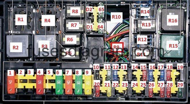
Fuse box diagram Ford Focus MK2 (Europe).
type 3.
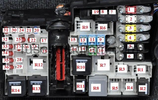
R1 | Starter motor inhibitor switch relay |
R2 | Horn relay |
3 | Reversing lamp relay |
R4 | – |
R5 | Exhaust gas recirculation (EGR) relay (petrol), fuel heater relay – (Diesel) |
R6 | – |
R7 | Heated windscreen relay |
R8 | Ignition main circuits relay |
R9 | Headlamp washer pump relay |
R10 | Heater blower relay |
R11 | Wide open throttle (WOT) relay – AC |
R12 | Engine coolant blower motor relay, glow plug relay – (Diesel) |
R13 | Starter motor relay |
R14 | Engine control (EC) relay |
F1 | (50A/60A) Engine coolant blower motor control module |
F2 | (80A) Power steering |
F3 | (60A) Fascia fuse box/relay plate F41/F43-F46/F48-F51/F55/F56/F59/F77, headlamps, windscreen wipers |
F4 | (60A) Fascia fuse box/relay plate F39/F40/F52/F57/F58/F62/F78-F83 |
F5 | (80A) Auxiliary heater 1 |
F6 | (60A) Glow plug control module |
F7 | (30A) Anti-lock brake system (ABS) |
F8 | (20A) Anti-lock brake system (ABS) |
F9 | (20A) Engine management |
F10 | (30A) Heater/air conditioning (AC) |
F11 | (20A) Ignition switch |
F12 | (40A) Ignition main circuits relay |
F13 | (20A) Starter motor relay |
F14 | (40A) Heated windscreen |
F15 | (30A) Engine coolant blower motor relay |
F16 | (40A) Heated windscreen |
F17 | (30A) Parking brake control module |
F18 | – |
F19 | (10A) Anti-lock brake system (ABS) |
F20 | (15A) Horn |
F21 | (20A) Auxiliary heater 2 |
F22 | (10A) Power steering |
F23 | (30A) Headlamp washers |
F24 | (15A) Fuel heater |
F25 | (10A) Fuel heater, headlamp washers, heated windscreen, reversing lamps, starter motor inhibitor switch relay, ignition main circuits relay, steering position sensor |
F26 | (10A) Transmission control module (TCM) |
F27 | (10A) Wide open throttle (WOT) relay – AC |
F28 | (10A) Engine management |
F29 | – |
F30 | (3A) Engine management, transmission control module (TCM) |
F31 | (10A) Alternator |
F32 | (10A) Transmission mode sensor, transmission control module (TCM) (1,8/2,0 Duratec-HE with AT, exhaust gasrecirculation (EGR) relay |
F34 | (10A) Engine management |
F35 | (10A) Engine management |
F36 | (10A) Engine management |