For the Lexus IS 200, Lexus IS 300 (toyota altezza) 1999, 2000, 2001, 2002, 2003, 2004, 2005 model year.
Fuse box in passenger compartment.
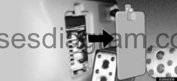
fuse box location.
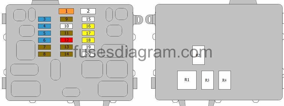
Driver’s side kick panel.
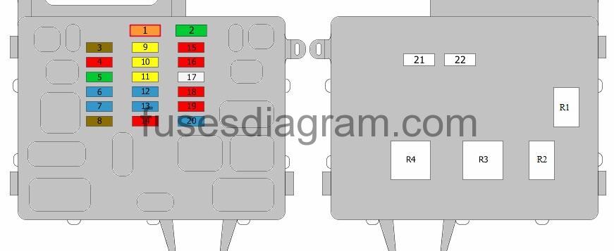
fuse box diagram.
Left hand drive.

legend.
| Fuse | Amps | Circuits protected |
|---|---|---|
| 1 | 40A | Demister Heated mirror(s) |
| 2 | 40A | AM 1 |
| 3 | 20A | Driver’s power window Communication system |
| 4 | 20A | Central and double locking Lights on Communication system Power windows Seat belt warning light Interior lights |
| 5 | 7,5A | Starting system Navigation system ECT Engine control Automatic transmission position indicator |
| 6 | 15A | Heated seats |
| 7 | 10A | Central and double locking Lights on Communication system Power windows Seat belt warning light Interior lights ABS Traction control Automatic air conditioning Sunroof Shift lock |
| 8 | 25A | Wash/wipe system |
| 9 | 10A | Front fog lights Tail lights |
| 10 | 7,5A | Combination meter Lights on Illumination Communication system Rear fog light Headlights |
| 11 | 20A | De-icer |
| 12 | 15A | Cigarette lighter |
| 13 | 10A | Supplemental restraint system (SRS) |
| 14 | 10A | Body control unit Electric mirrors Audio system Security system |
| 15 | 10A | Combination meter Cruise control ABS Traction control Reversing lights Tail lights Brake lights Hazard warning lights Direction indicators Lights on Seat belt warning light Communication system Navigation system Demister Heated mirror(s) De-icer ECT Engine control Telephone Shift lock Alternator Power windows |
| 16 | 15A | Wash/wipe system Headlight washers |
| 17 | 10A | Automatic air conditioning |
| 18 | 30A | Sunroof |
| 19 | 15A | Brake lights ABS Traction control ECT Engine control Cruise control Shift lock Automatic transmission position indicator |
| 20 | Not used | |
| 21 | Noise filter | |
| 22 | Noise filter | |
| R1 | De-icer relay | |
| R2 | Tail light relay | |
| R3 | Demister relay | |
| R4 | Flasher relay |
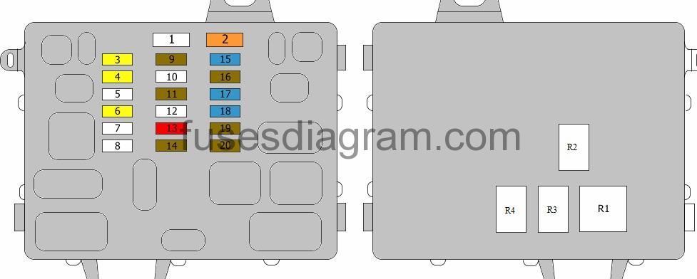
Driver’s side kick panel.
fuse box diagram.
Right hand drive.
legend.
| Fuse | Amps | Circuits protected |
|---|---|---|
| 1 | 40 | AM 1 |
| 2 | 30 | Demister Heated mirror(s) |
| 3 | 7,5 | Combination meter Lights on Illumination Communication system Rear fog light Security system |
| 4 | 10 | Front fog lights Tail lights |
| 5 | 30 | Sunroof |
| 6 | 15 | Brake lights ABS Traction control ECT Engine control Cruise control Shift lock Automatic transmission position indicator |
| 7 | 15 | 12V socket |
| 8 | 7,5 | Starting system Navigation system ECT Engine control Automatic transmission position indicator |
| 9 | 20 | Central and double locking Lights on Communication system Power windows Seat belt warning light Interior lights |
| 10 | 20 | De-icer |
| 11 | 20 | Driver’s power window Communication system |
| 12 | 15 | Wash/wipe system Headlight washers |
| 13 | 15 | Cigarette lighter |
| 14 | 10 | Supplemental restraint system (SRS) |
| 15 | 10 | Central and double locking Lights on Communication system Power windows Seat belt warning light Interior lights ABS Traction control Automatic air conditioning Sunroof Shift lock |
| 16 | 10 | Combination meter Cruise control ABS Traction control Reversing lights Tail lights Brake lights Hazard warning lights Direction indicators Lights on Seat belt warning light Communication system Navigation system Demister Heated mirror(s) De-icer ECT Engine control Telephone Shift lock Alternator Power windows |
| 17 | 25 | Wash/wipe system |
| 18 | 10 | Automatic air conditioning |
| 19 | 10 | Body control unit Electric mirrors Audio system Security system |
| 20 | 15 | Heated seats |
| 21 | Noise filter | |
| 22 | Noise filter | |
| R1 | Tail light relay | |
| R2 | De-icer relay | |
| R3 | Demister relay | |
| R4 | Flasher relay |
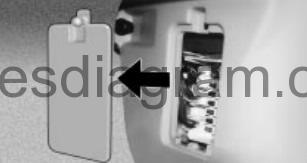
Passenger’s side kick panel.
fuse box location.
fuse box diagram.
Left hand drive.
legend.
| Fuse | Amps | Circuits protected |
|---|---|---|
| 1 | 40A | Automatic air conditioning |
| 2 | Not used | |
| 3 | 15A | Central and double locking |
| 4 | 15A | Front fog lights |
| 5 | 15A | 12V socket |
| 6 | 15A | Demister Heated mirror(s) |
| 7 | 7,5A | Supplemental restraint system (SRS) Combination meter Interior lights Communication system |
| 8 | 7,5A | Engine control Supplemental restraint system (SRS) |
| 9 | 7,5A | Interior lights Communication system Door lock control |
| 10 | Not used | |
| 11 | 7,5A | Rear fog light Headlights |
| 12 | 10A | Automatic air conditioning Combination meter Interior lights Communication system Central and double locking Door lock control Lights on Seat belt warning light Clock Power windows |
| 13 | 7,5A | Navigation system |
| 14 | 7,5A | Cruise control ECT Engine control Automatic transmission position indicator Supplemental restraint system (SRS) |
| 15 | Not used | |
| 16 | 20A | Power window, passenger’s side Communication system |
| 17 | 20A | Rear left power window Communication system |
| 18 | 20A | Rear right power window Communication system |
| 19 | Not used | |
| 20 | Not used | |
| R1 | Air-conditioning relay | |
| R2 | Front fog light relay | |
| R3 | Heated mirror relay | |
| R4 | Power window relay |
Passenger’s side kick panel.
fuse box diagram
Right hand drive.
legend.
| Fuse | Amps | Circuits protected |
|---|---|---|
| 1 | Not used | |
| 2 | 40A | Automatic air conditioning |
| 3 | 20A | Power window, passenger’s side Communication system |
| 4 | 20A | Rear right power window Communication system |
| 5 | Not used | |
| 6 | 20A | Rear left power window Communication system |
| 7 | Not used | |
| 8 | Not used | |
| 9 | 7,5A | Cruise control ECT Engine control Automatic transmission position indicator Supplemental restraint system (SRS) |
| 10 | Not used | |
| 11 | 7,5A | Interior lights Communication system Door lock control |
| 12 | Not used | |
| 13 | 10A | Automatic air conditioning Combination meter Interior lights Communication system Central and double locking Door lock control Lights on Seat belt warning light Clock Power windows Light control Security system |
| 14 | 7,5A | Rear fog light Security system |
| 15 | 15A | Central and double locking |
| 16 | 7,5 | Navigation system |
| 17 | 15A | Front fog lights |
| 18 | 15A | Demister Heated mirror(s) |
| 19 | 7,5A | Supplemental restraint system (SRS) Combination meter Interior lights Communication system |
| 20 | 7,5A | Engine control Supplemental restraint system (SRS) |
| R1 | Air-conditioning relay | |
| R2 | Front fog light relay | |
| R3 | Heated mirror relay | |
| R4 | Power window relay |
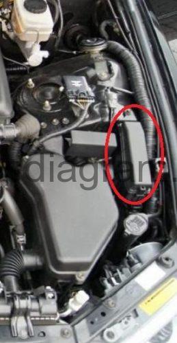
Fuse box in engine compartment.
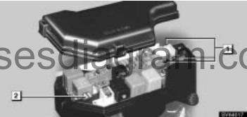
Turn the ignition switch off and open the fuse box lid.
fuse box layout.
Left hand drive.

Right hand drive.
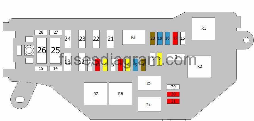
legend.
| Fuse | Amps | Circuits protected |
|---|---|---|
| 1 | 40A | Main power supply |
| 2 | 20A | Fuse box |
| 3 | Not used | |
| 4 | 7,5A | Alternator |
| 5 | 15A | Cruise control ECT Engine control Automatic transmission position indicator |
| 6 | 20A | Ignition Starting Engine control |
| 7 | 10A | Horn Security system (RHD) |
| 8 | Not used | |
| 9 | 20A | Audio system |
| 10 | 15A (LHD) 10A (RHD) | Direction indicators Hazard warning lights |
| 11 | 25A | Electronic fuel injection Cruise control ECT Engine control Immobiliser |
| 12 | 30A | Electric seats |
| 13 | 30A | Headlight washer |
| 14 | Not used | |
| 15 | Not used | |
| 16 | Not used | |
| 17 | 7,5A (LHD) 10A (RHD) | Daylight running system (LHD) Headlight leveling (RHD) |
| 18 | 15A | Left dipped beam |
| 19 | 15A | Right dipped beam |
| 20 | 7,5A | ABS Or ESP control unit |
| 21 | Not used | |
| 22 | Not used | |
| 23 | 30A | Condenser fan |
| 24 | 30A | Cooling fan |
| 25 | 120A | Alternator |
| 26 | 60A | ABS Traction control |
| 27 | Not used | |
| 28 | Not used | |
| 29 | 10A | Left main beam |
| 30 | 10A | Right main beam |
| 31 | 10A | Headlight levelling (LHD) Left main beam (RHD) |
| R1 | Headlight relay (LHD) Starter relay (RHD) | |
| R2 | Starter relay (LHD) Headlight relay (RHD) | |
| R3 | Circuit opening relay | |
| R4 | Electronic fuel injection relay | |
| R5 | Horn relay | |
| R6 | ABS motor relay | |
| R7 | ABS solenoid relay |
Relay box in engine compartment.
relay box location.
relay box diagram.

Relay R1 – Fuel pump relay, Additional relay, fuel pump
Relay R2 – Dimmer relay
Relay R3 – Air-conditioning compressor relay or Horn
Relay R4 – Cooling fan 3 relay
Relay R5 – Cooling fan 2 relay
Relay R6 – Cooling fan 1 relay